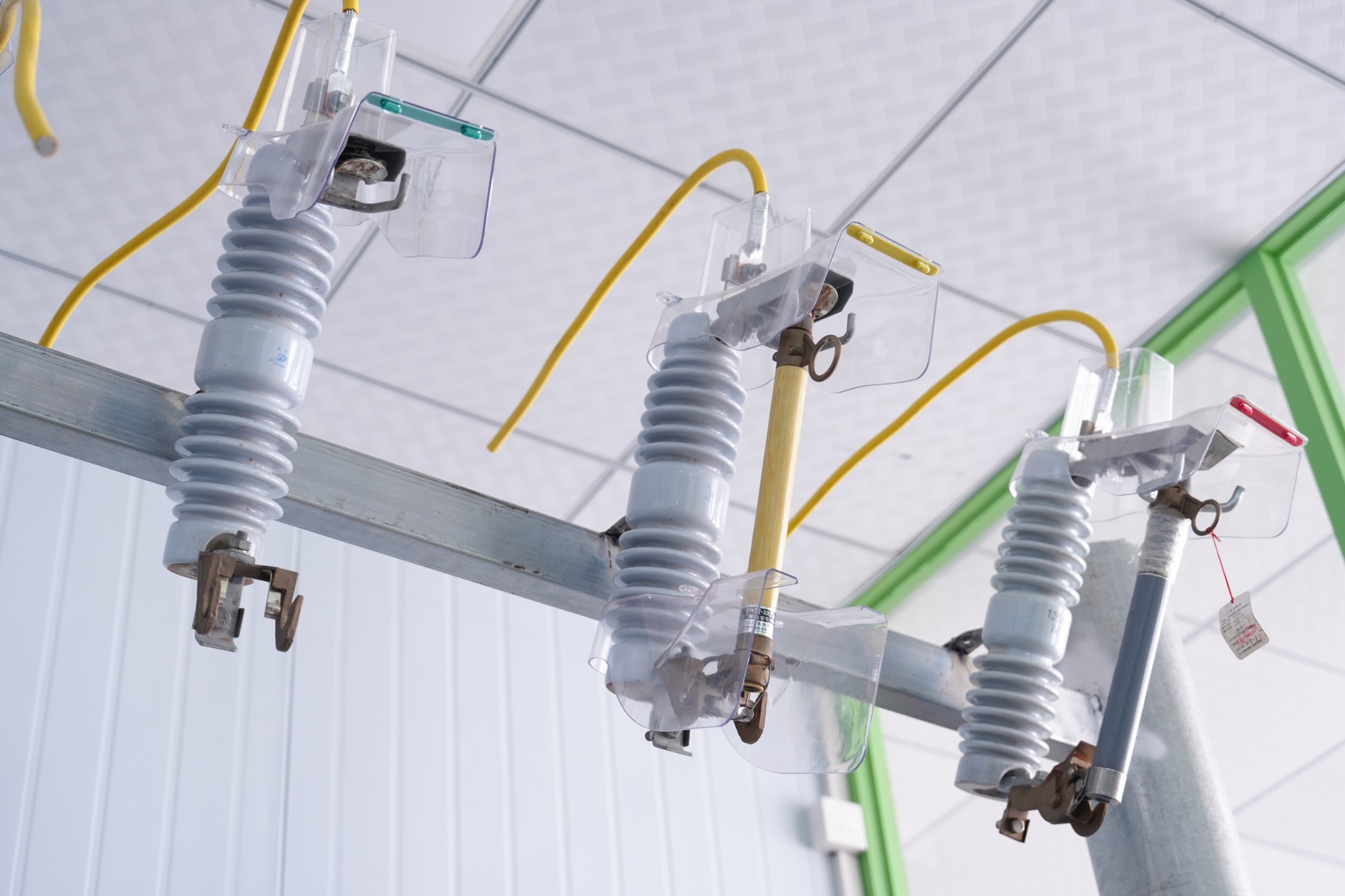
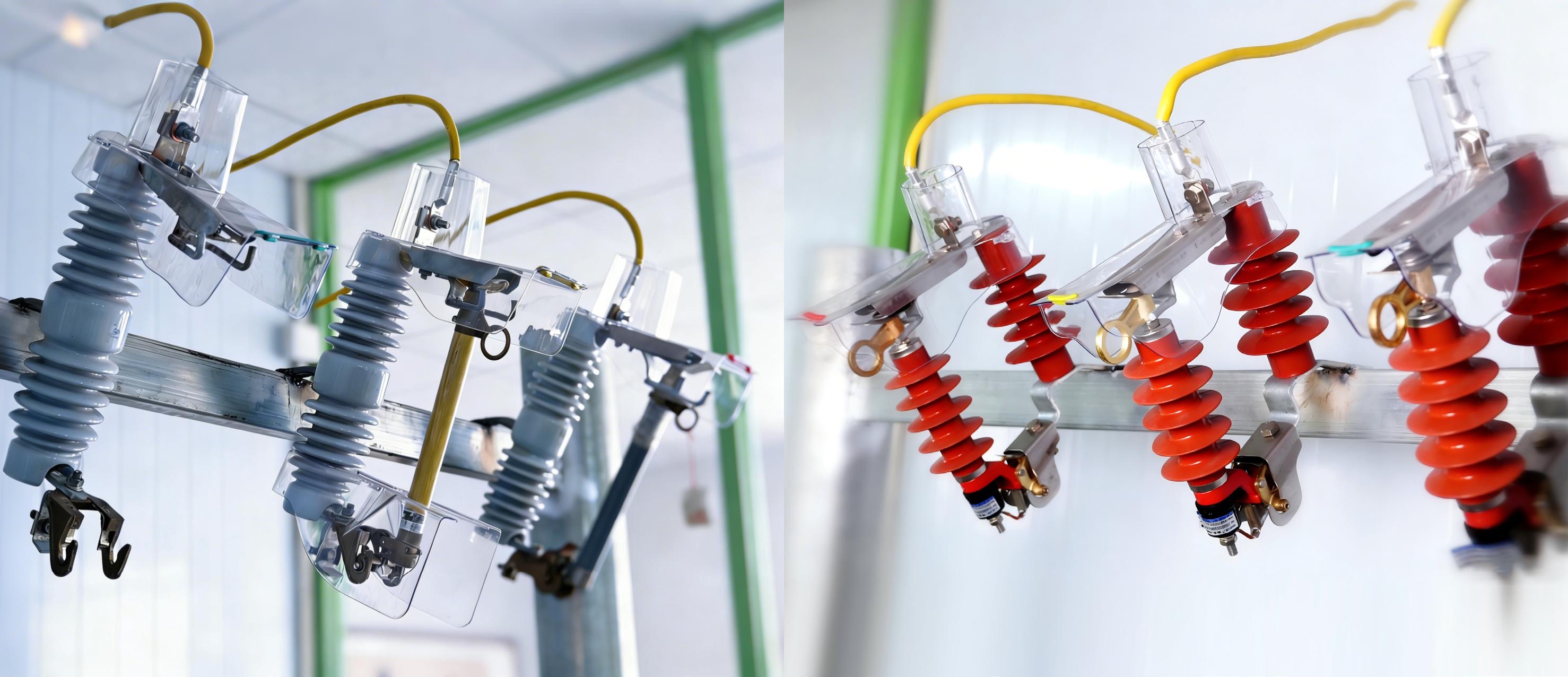
DIANLETE transparent insulation protective covers installed on gray and red 10kV equipment configurations
Visible protection for critical power connections

DIANLETE

Protection you can inspect.

Transparent 10kV insulation covers engineered for live-line inspection, phase identification and safer installation.

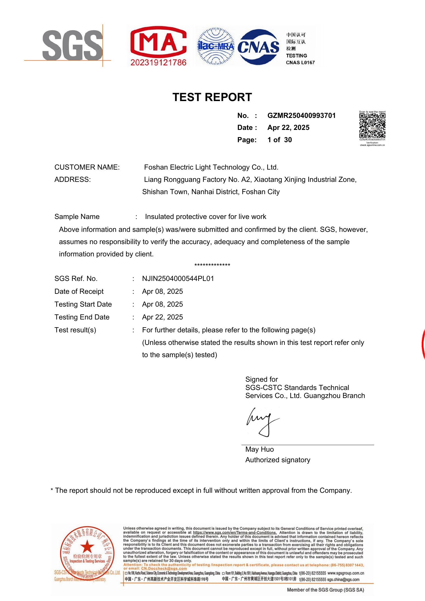
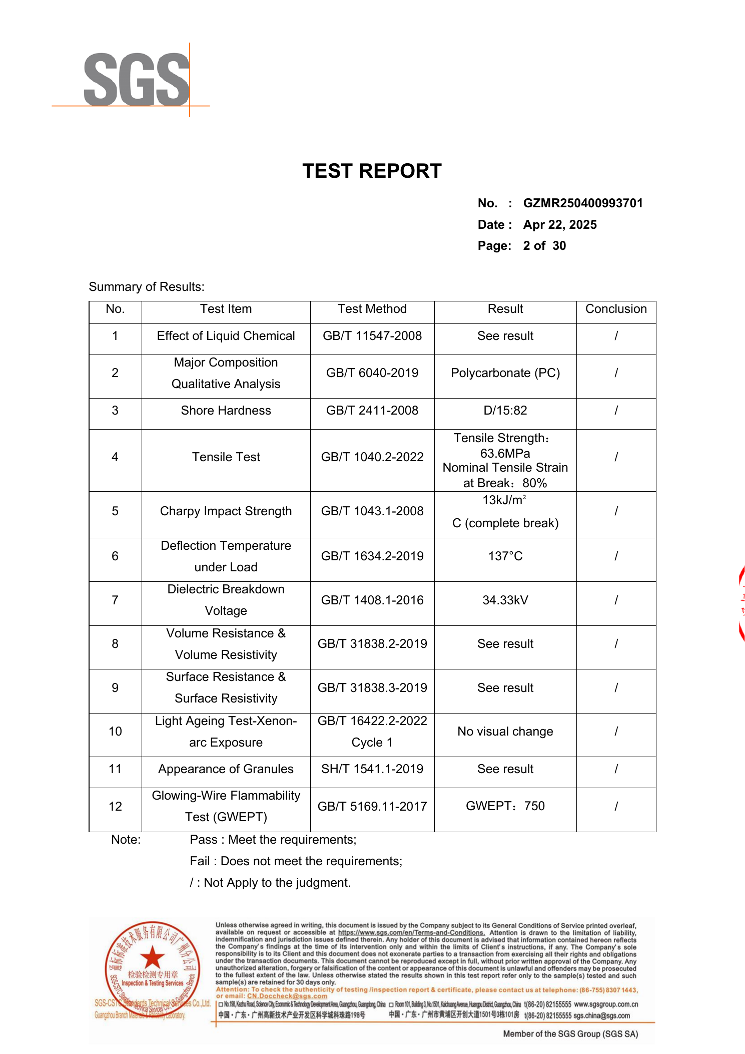
SGS test report GZMR250400993701

SGS Tested. Proven Performance.

34.33kVPower-frequency withstand voltage
137°CContinuous operating temperature
750°CShort-circuit withstand temperature

TEST REPORT: GZMR250400993701

Engineered to Fit. Color-Coded for Safety.

01Photo / Drawing
Equipment photo submitted for insulation cover customization
02Fit Analysis
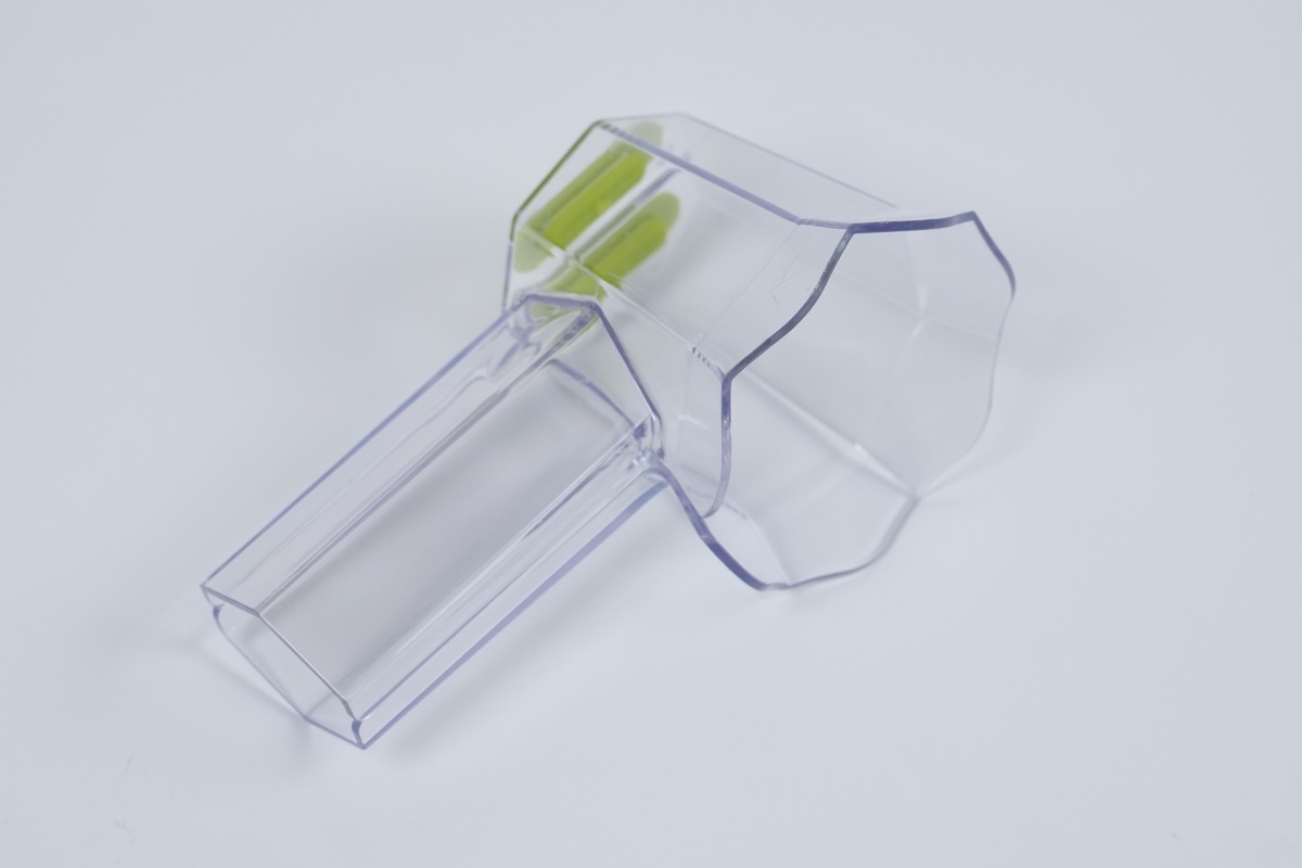
Transparent insulation cover geometry analysis
03Color-Coded Design
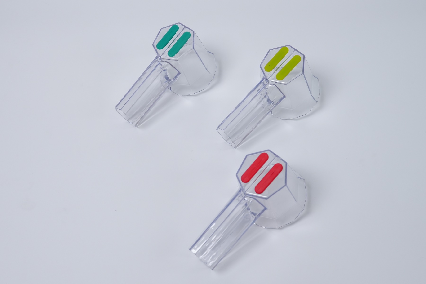
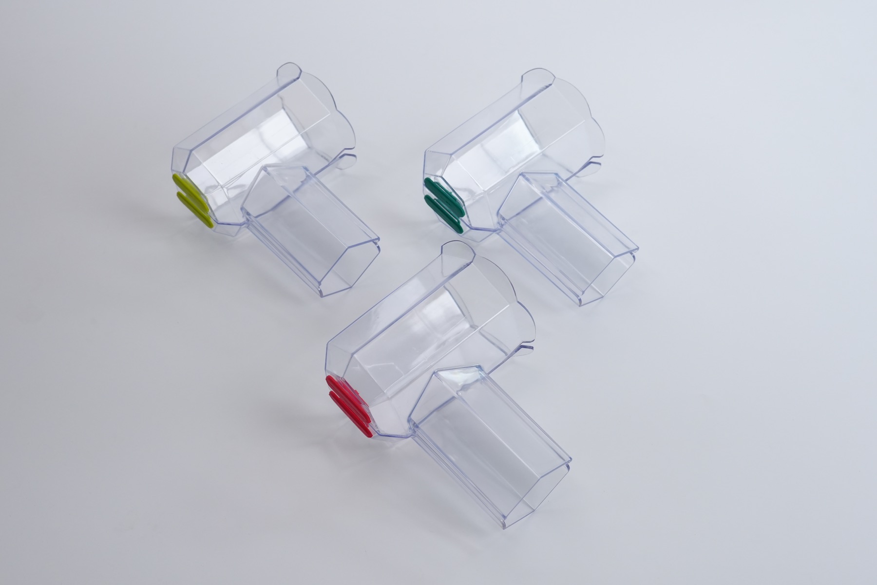
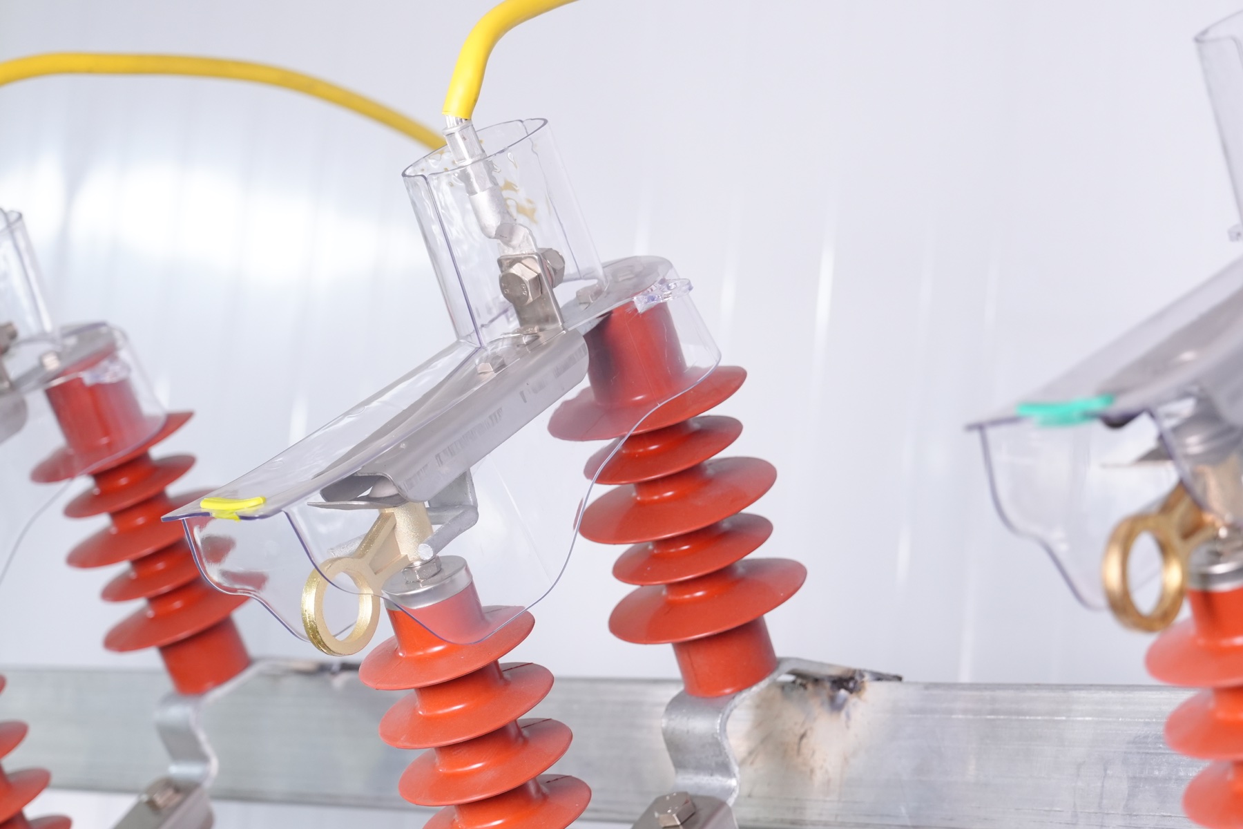
Red yellow and green phase-coded insulation cover design
04Sample
Transparent insulation protective cover sample
05Production
Color-coded insulation covers in production application

Three-Phase System (3P)

L1 / Phase A
L2 / Phase B
L3 / Phase C

Three-Phase Four-Wire System (3P4W)

L1 / Phase A
L2 / Phase B
L3 / Phase C
N / Neutral

Color-coded installation enables fast visual identification and helps reduce phase identification and operating risk.

PDF Product Portfolio

Visible Insulation Covers for Critical 10kV Connections.

Product names, dimensions and technical visuals below are taken directly from the original DIANLETE electronic catalog and can be updated as product documentation evolves.

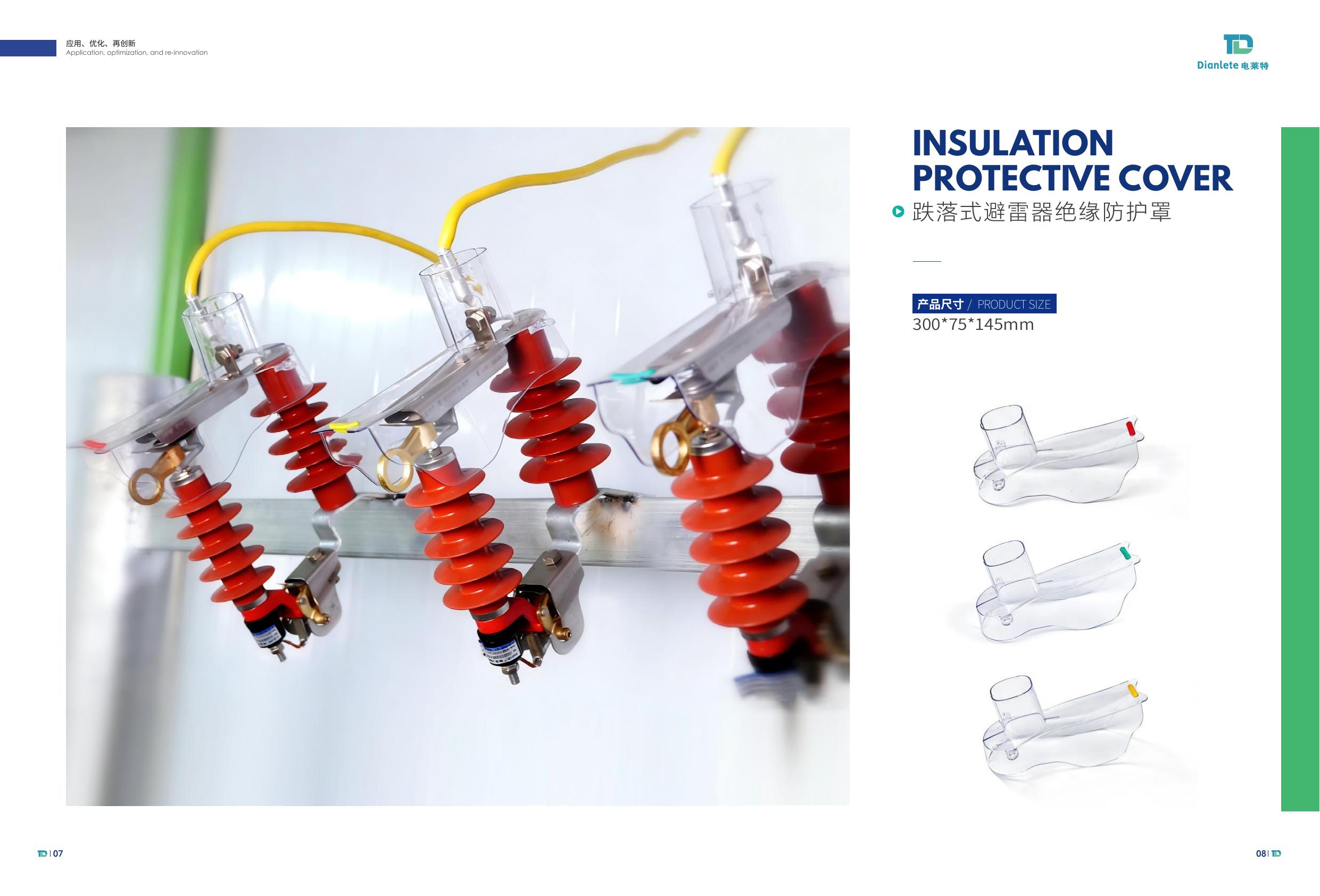
PDF catalog page for drop-out arrester insulation protective cover
10kV / Arrester

Drop-Out Arrester Insulation Protective Cover

Product size300 × 75 × 145 mm
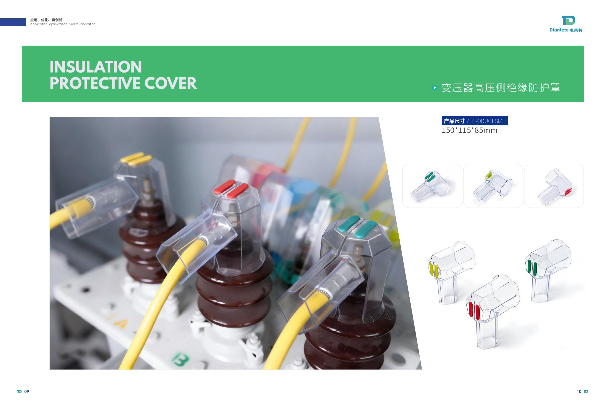
PDF catalog page for transformer high-voltage side insulation protective cover
10kV / Transformer

Transformer High-Voltage Side Insulation Protective Cover

Product size150 × 115 × 85 mm
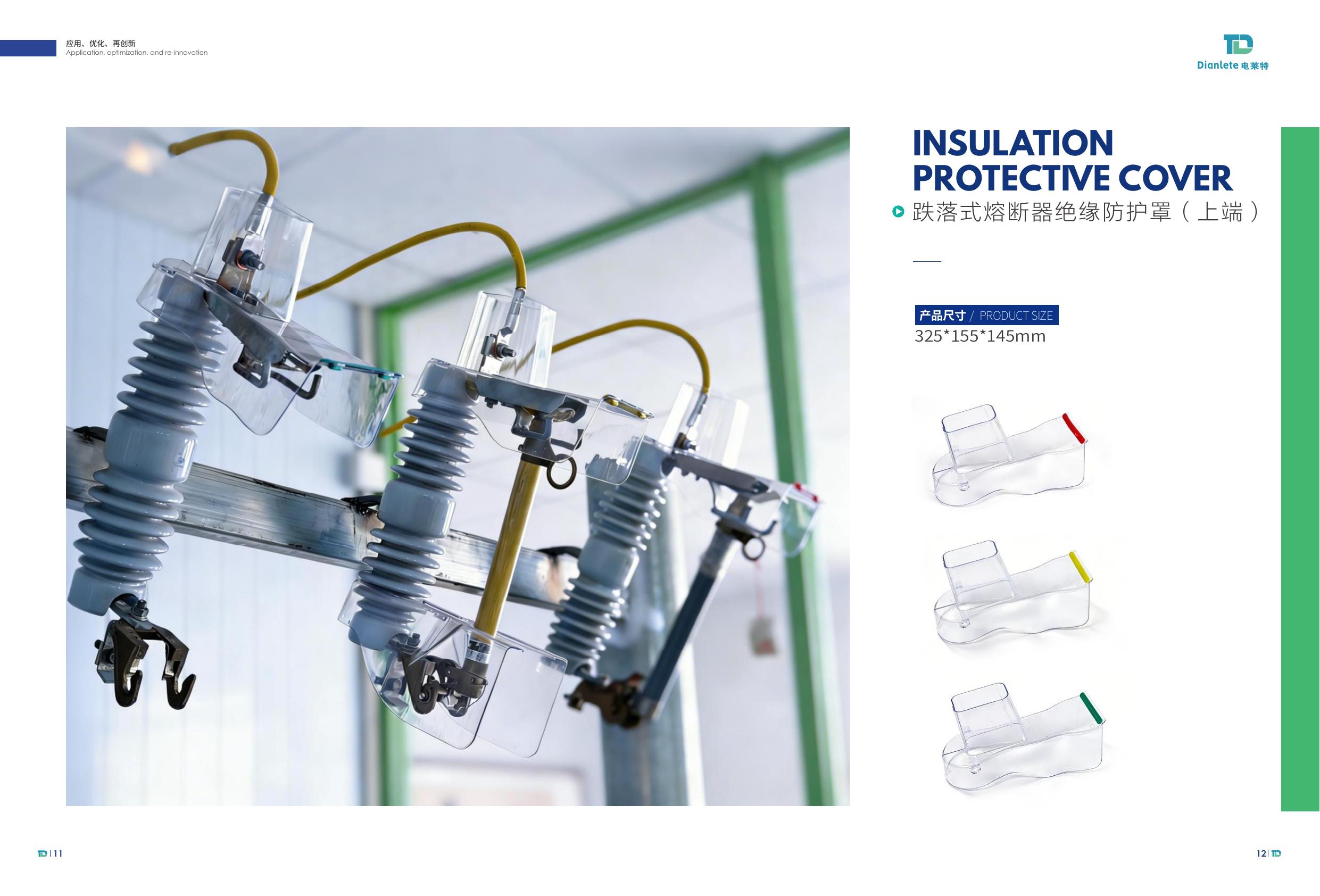
PDF catalog page for upper-terminal drop-out fuse insulation protective cover
10kV / Fuse Upper

Drop-Out Fuse Upper-Terminal Insulation Protective Cover

Product size325 × 155 × 145 mm
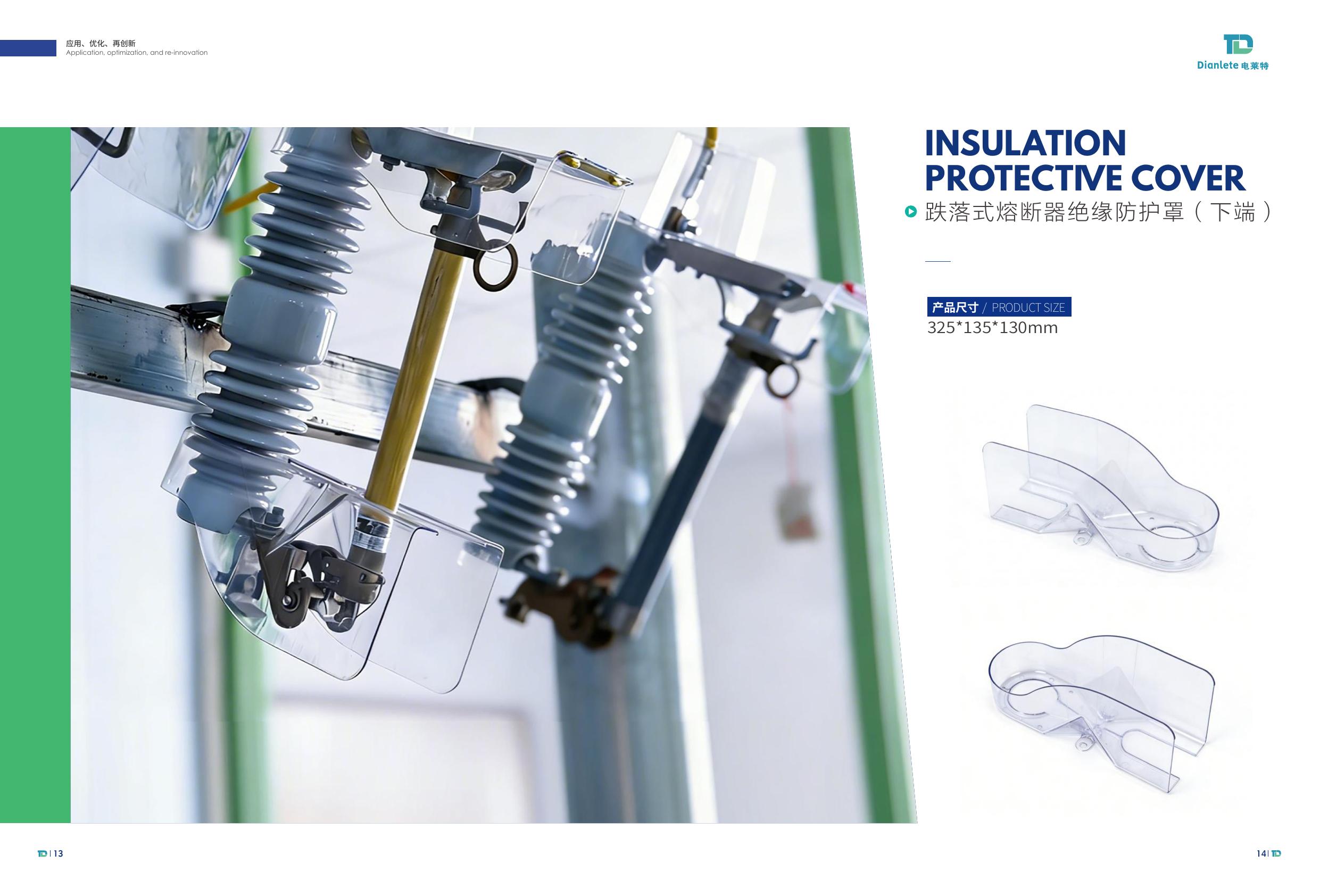
PDF catalog page for lower-terminal drop-out fuse insulation protective cover
10kV / Fuse Lower

Drop-Out Fuse Lower-Terminal Insulation Protective Cover

Product size325 × 135 × 130 mm
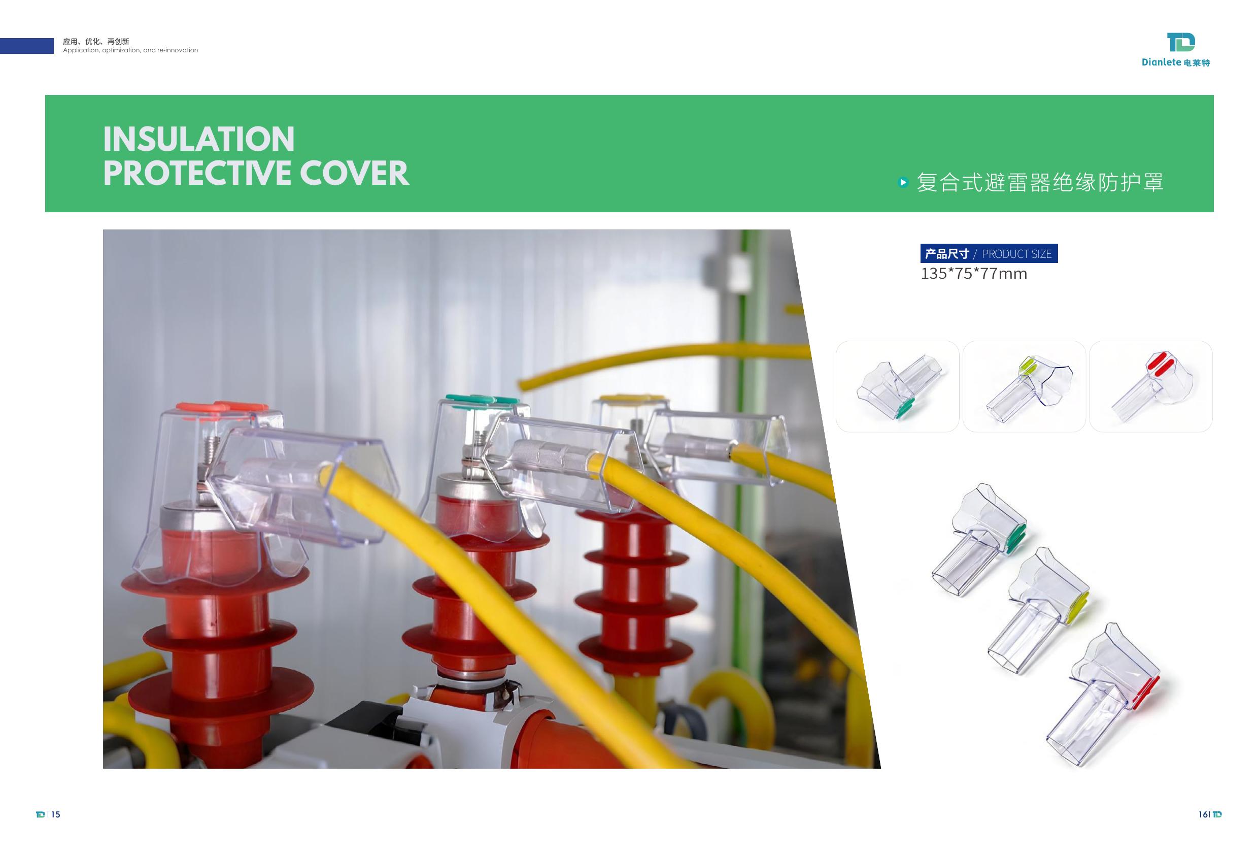
PDF catalog page for composite arrester insulation protective cover
10kV / Composite Arrester

Composite Arrester Insulation Protective Cover

Product size135 × 75 × 77 mm
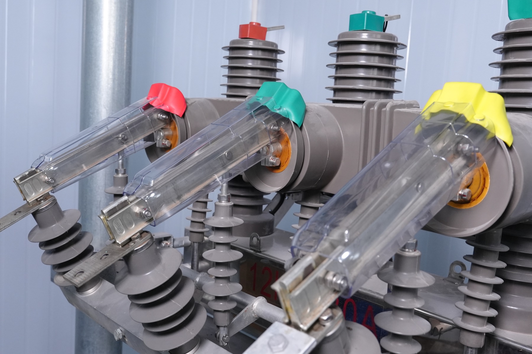
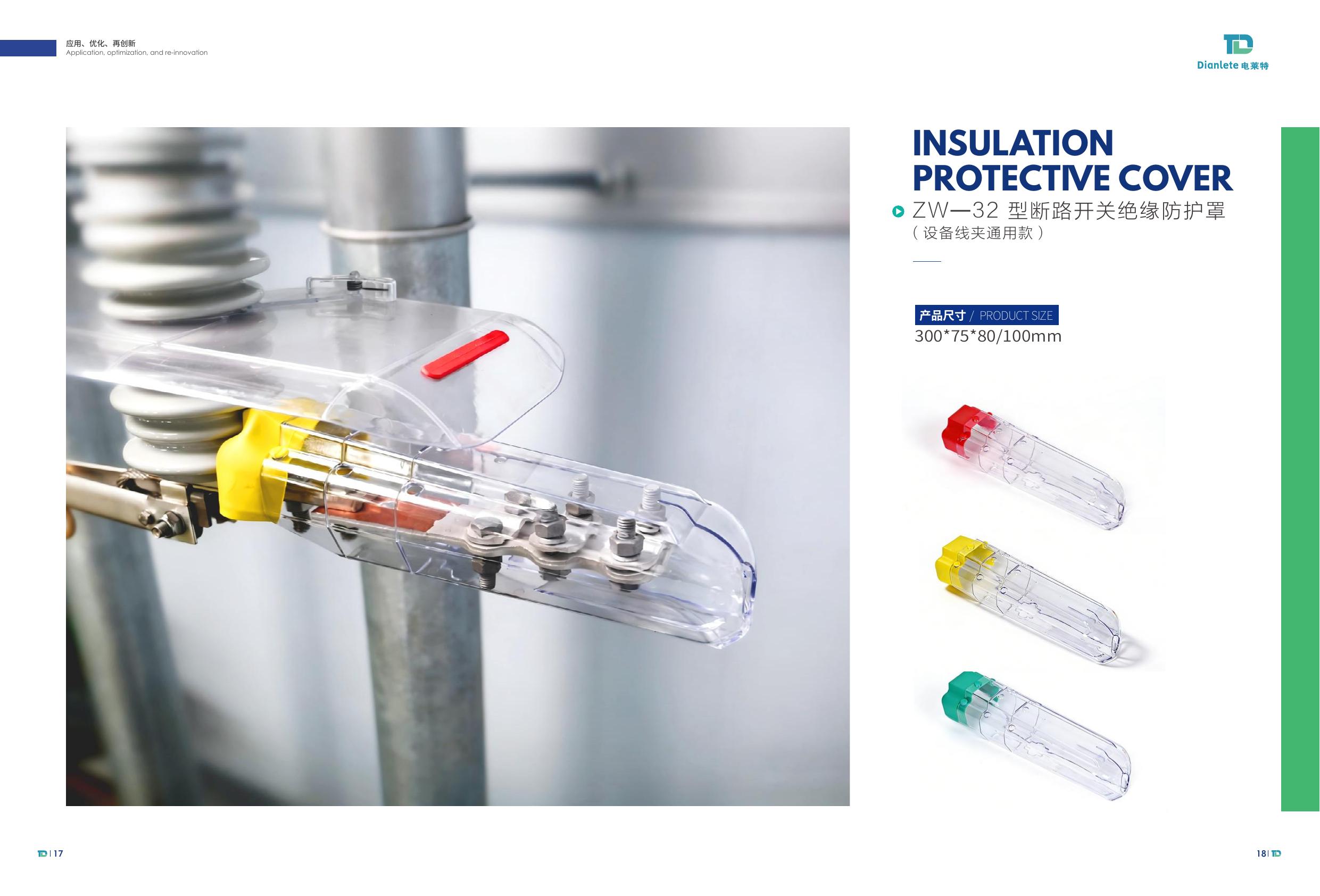
PDF catalog page for ZW-32 circuit breaker switch insulation protective cover
10kV / ZW-32 Switch

ZW-32 Circuit Breaker Switch Insulation Protective Cover

Product size300 × 75 × 80/100 mm

Four primary product systems are shown on the homepage. Open the product directory for every available cover, dimension and purchasing route.

View All Products

More Products from the Original PDF

Pages 11-17 · Select any page to inspect the original dimensions and diagrams.

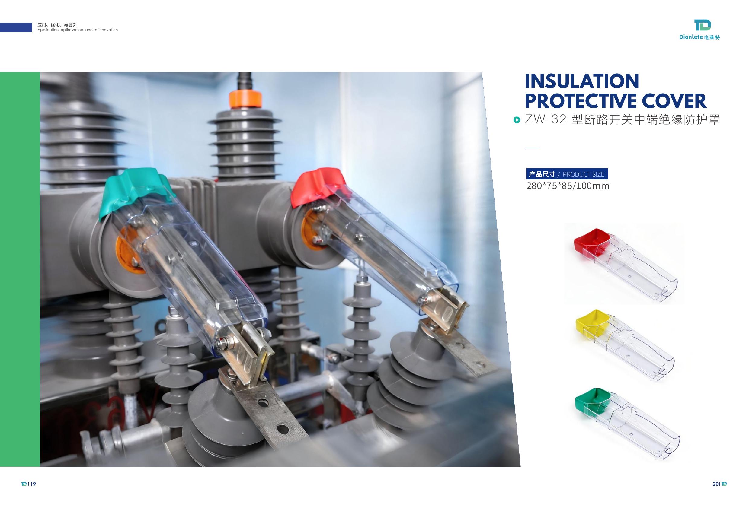
ZW-32 circuit breaker switch mid-terminal insulation protective cover
10kV / ZW-32 Mid-Terminal

ZW-32 Circuit Breaker Switch Mid-Terminal Insulation Protective Cover

280 × 75 × 85/100 mm
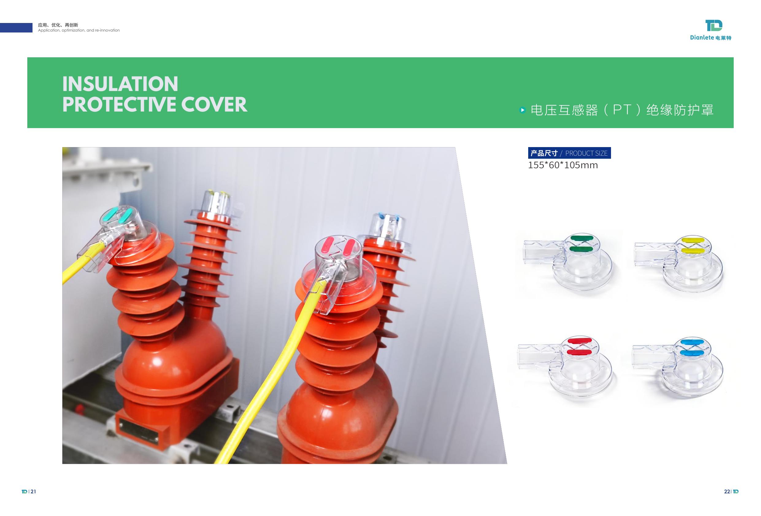
Voltage transformer PT insulation protective cover
10kV / Voltage Transformer

Voltage Transformer (PT) Insulation Protective Cover

155 × 60 × 105 mm
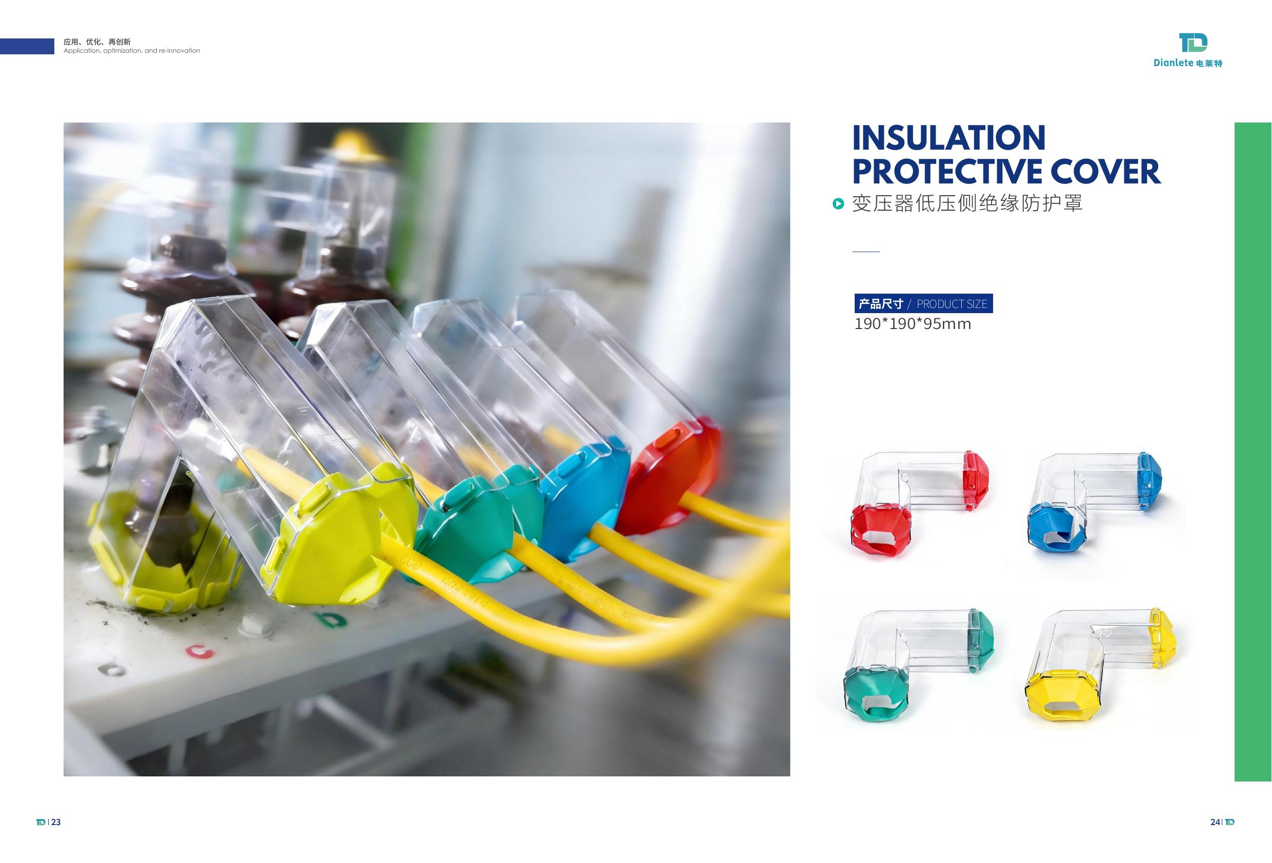
Transformer low-voltage side insulation protective cover
10kV / Transformer LV Side

Transformer Low-Voltage Side Insulation Protective Cover

190 × 190 × 95 mm
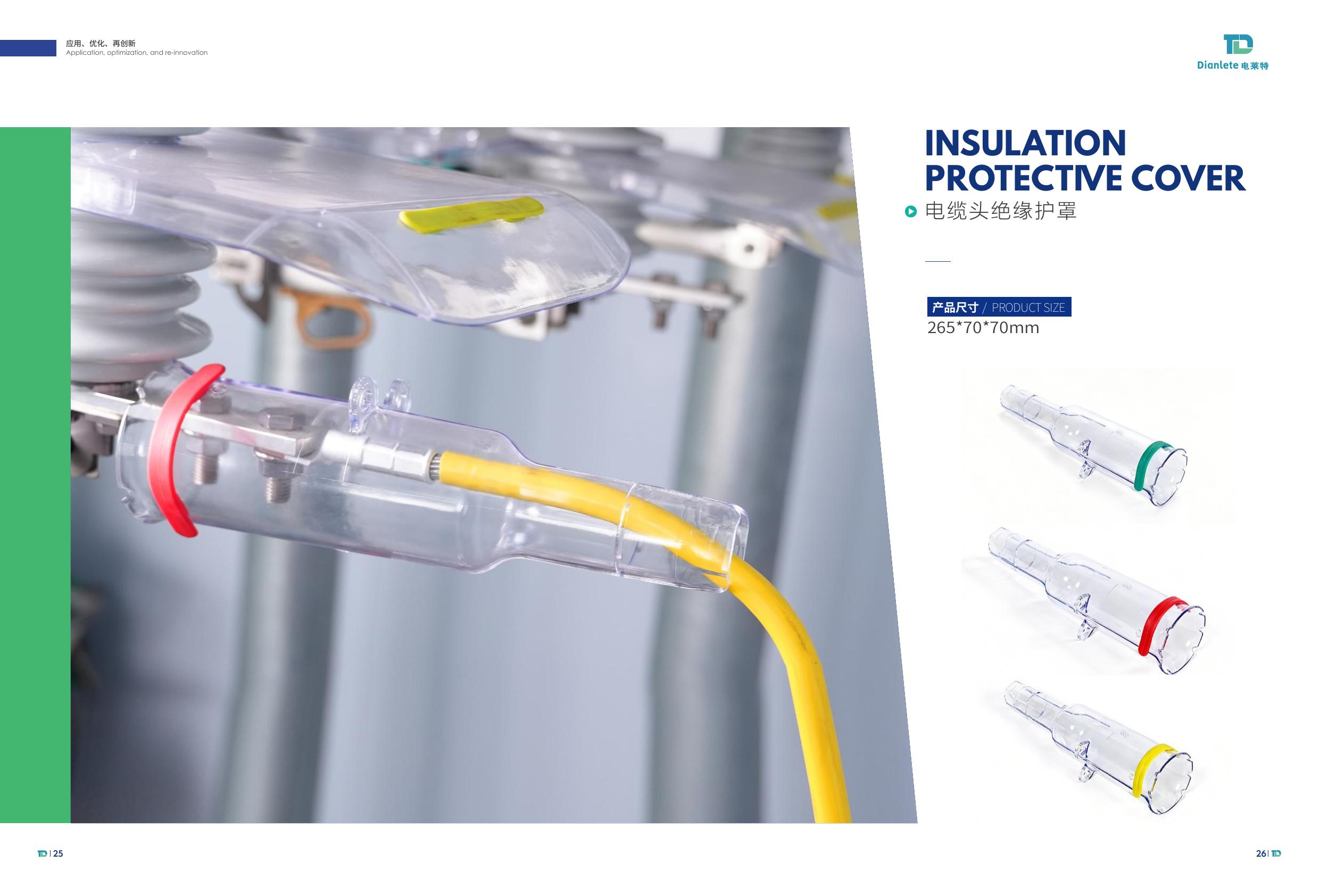
Cable terminal insulation protective cover
10kV / Cable Terminal

Cable Terminal Insulation Protective Cover

265 × 70 × 70 mm
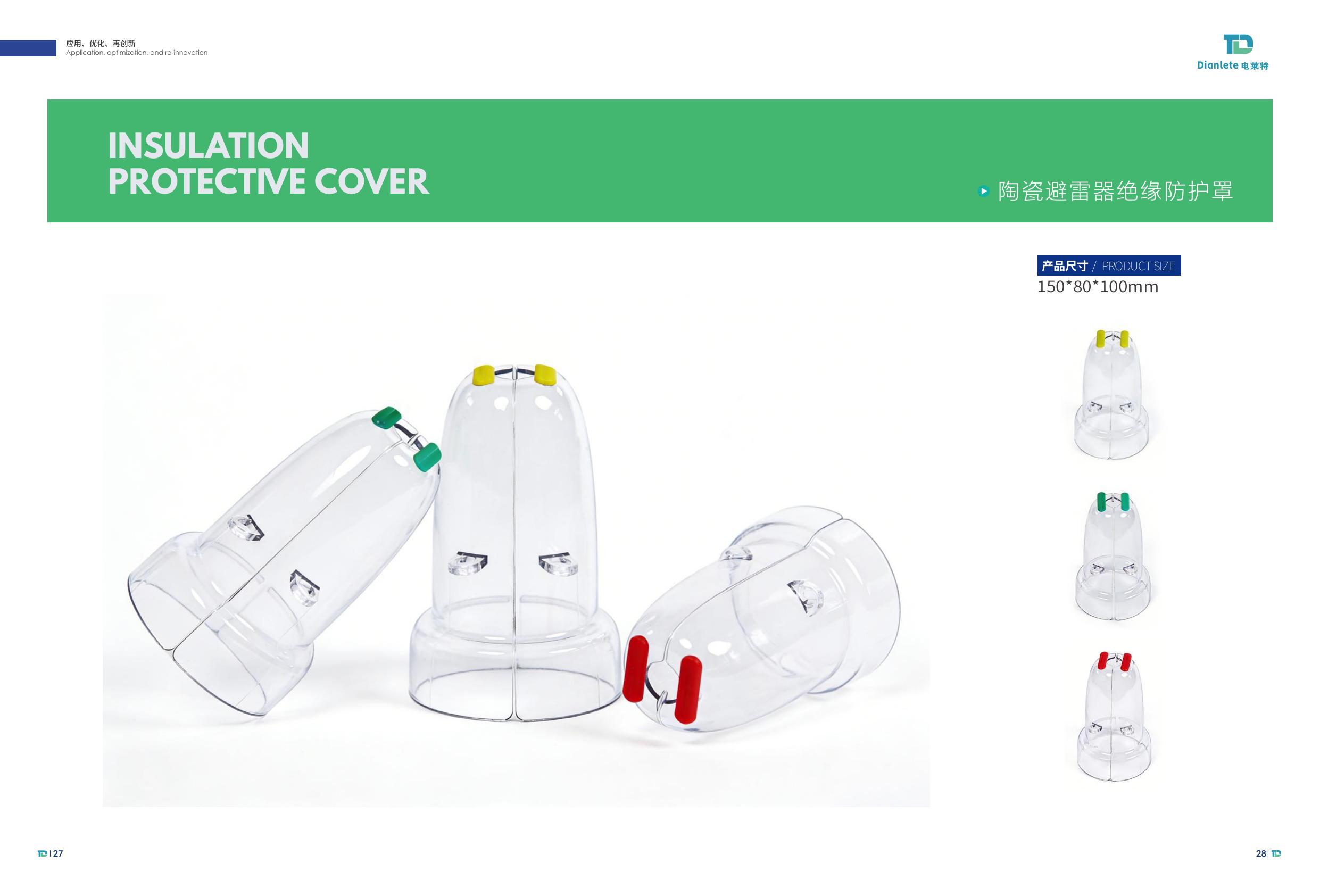
Porcelain lightning arrester insulation protective cover
10kV / Porcelain Arrester

Porcelain Lightning Arrester Insulation Protective Cover

150 × 80 × 100 mm
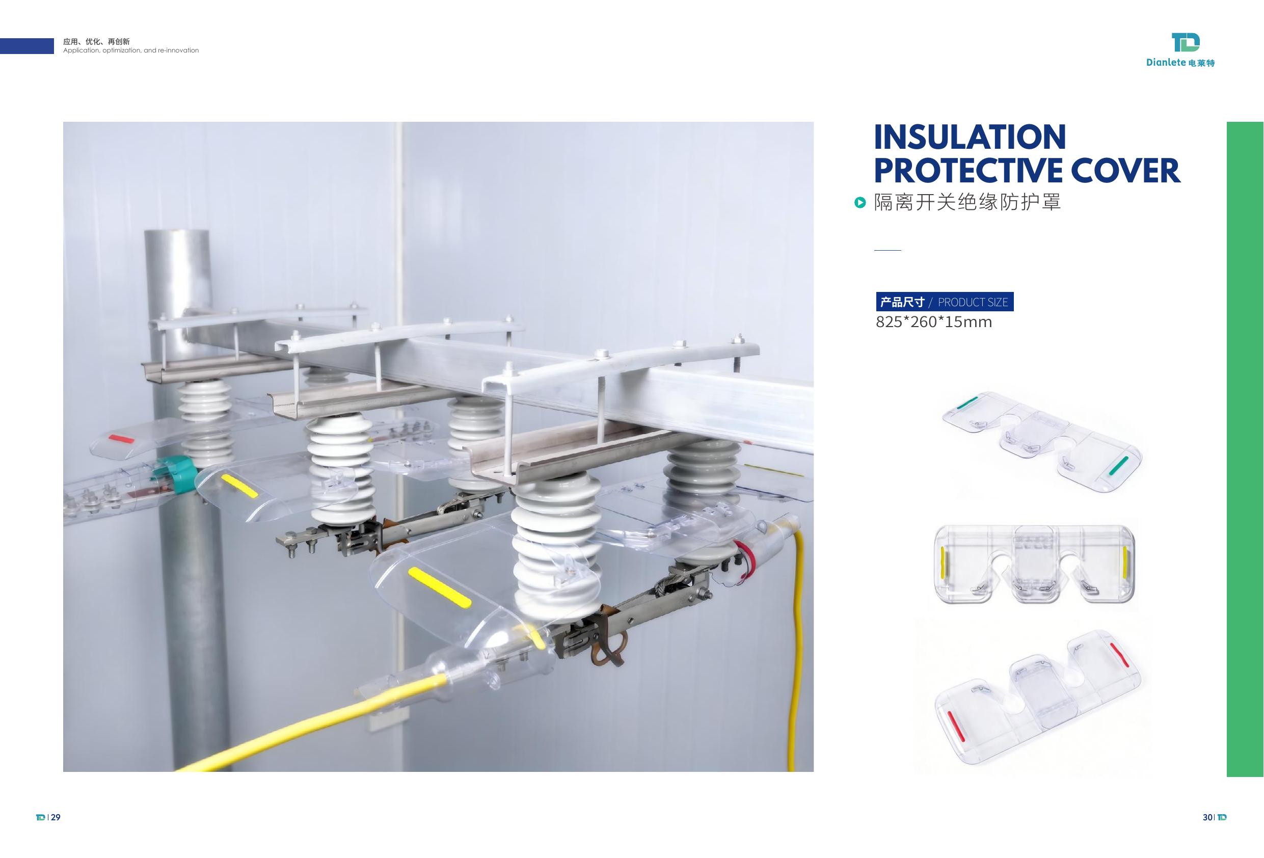
Disconnector switch insulation protective cover
10kV / Disconnector

Disconnector Switch Insulation Protective Cover

825 × 260 × 15 mm
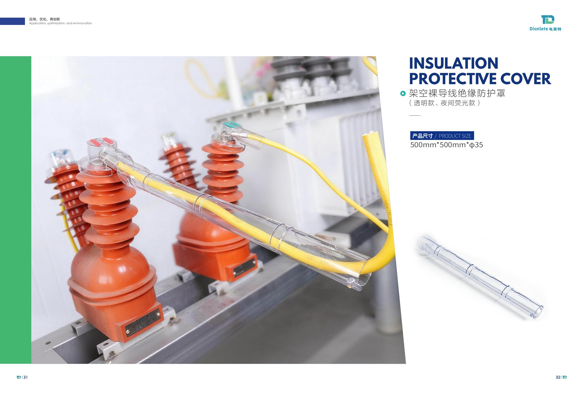
Overhead bare conductor insulation protective cover
Overhead Conductor / Transparent or Fluorescent

Overhead Bare Conductor Insulation Protective Cover

500 × 500 × Ø35 mm

Retail prices, stock status and payment checkout will be activated after the final SKU, currency and selling price list is confirmed. Product specifications remain subject to final catalog and engineering verification.

SGS tested performance summary for live-work insulation protective cover
SGS Tested Material Performance

Technical evidence before product claims.

The submitted sample is identified in the SGS report as an “Insulated protective cover for live work.” The tested polycarbonate material provides a documented technical basis for DIANLETE visible insulation protection solutions.

34.33kVDielectric breakdown voltage
137°CDeflection temperature under load
63.6MPaTensile strength
750°CGlow-wire flammability test
Open the Full Test Report
Core Technology

Visibility engineered into protection.

Traditional opaque covers can conceal critical connection points. DIANLETE visible insulation protective covers keep installation position, phase identification and equipment condition easier to observe while providing targeted protection around exposed interfaces.

Transparent insulation protective cover product
CLEAR VISUAL ACCESS
CUSTOM FIT GEOMETRY
Visible Insulation System

Visible installation. Precise protection.

Designed around real 10kV equipment geometry, each transparent cover balances insulation performance, live-line work requirements, installation efficiency and visual inspection access.

01
Transparent structureCritical interfaces remain visible during routine inspection.
02
Live-line operation focusedProtective structures developed for demanding energized equipment environments.
03
Phase-error prevention by designRed, yellow and green identifiers correspond to L1/L2/L3 or A/B/C for faster, more consistent installation.
04
Factory-controlled PC formulationMaterial and structure can be adapted for high UV exposure, heat, cold and project-specific conditions.
Start a Technical Inquiry
Color-Coded Visual Installation

Three-phase or three-phase four-wire identification at a glance.

Color-separated components make each phase easier to distinguish during installation and inspection. Combined with a transparent protective structure, technicians can confirm position and phase more directly, helping reduce identification errors and improve operational safety.

01
Easier phase recognition

Distinct colors make three-phase and three-phase four-wire groups faster to identify.

02
More visible installation

Transparent covers keep internal connection and fitting position observable.

03
Safer inspection workflow

Clear visual confirmation supports more consistent installation and maintenance checks.

PHASE IDENTIFICATION CONFIGURATIONS
3-PHASE
4-PHASE

Color configuration can be matched to local utility standards and project requirements.

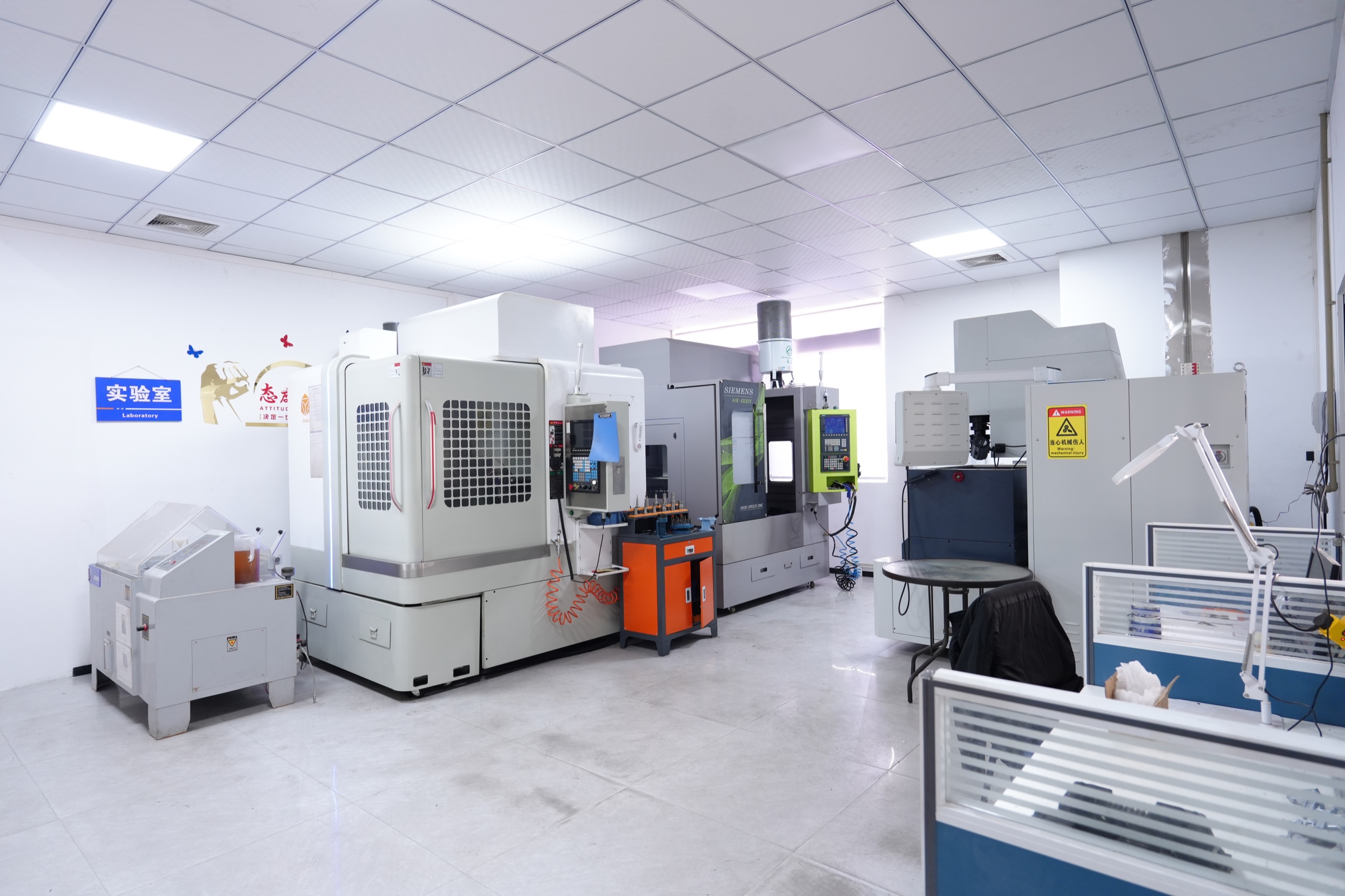
DIANLETE laboratory with precision machining and testing equipment
Field Application

Visible protection designed around energized equipment.

Survey & requirement review

Match equipment type, connection geometry and operational needs.

Engineering & prototyping

Develop fit, visibility and fastening details for the application.

Production & delivery

Scalable manufacturing for project orders and distributor supply.

Global Wildlife Protection

Animal contact protection for exposed power equipment.

DIANLETE develops equipment-specific insulation covers and wildlife protection guards intended to help limit access to energized interfaces and reduce animal contact-related short-circuit, flashover and outage risks across global utility environments.

01
SQUIRREL PROTECTION

Squirrel guards for electrical equipment

Custom-fit transparent covers for transformer terminals, arresters, switches and other exposed interfaces where squirrels and climbing animals may create contact paths.

02
BIRD & WILDLIFE PROTECTION

Bird protection for substations and overhead equipment

Protective cover geometry can be evaluated for bird contact, nesting exposure and wildlife access around pole-top and substation connection points.

03
SMALL-ANIMAL GUARDS

Equipment-specific animal protection covers

OEM and ODM development for local species, equipment dimensions, voltage class, UV exposure, temperature and project installation requirements worldwide.

10kV
15kV

Wildlife protection is engineered by equipment and project.

Submit equipment photos or drawings so cover geometry, clearances, fastening, material and environmental conditions can be reviewed. Voltage class and applicable certification requirements are confirmed separately for each market and project.

Upload Equipment
Technical Resources

Factory, certificates and project evidence.

Real Manufacturing Site

From factory campus to precision production.

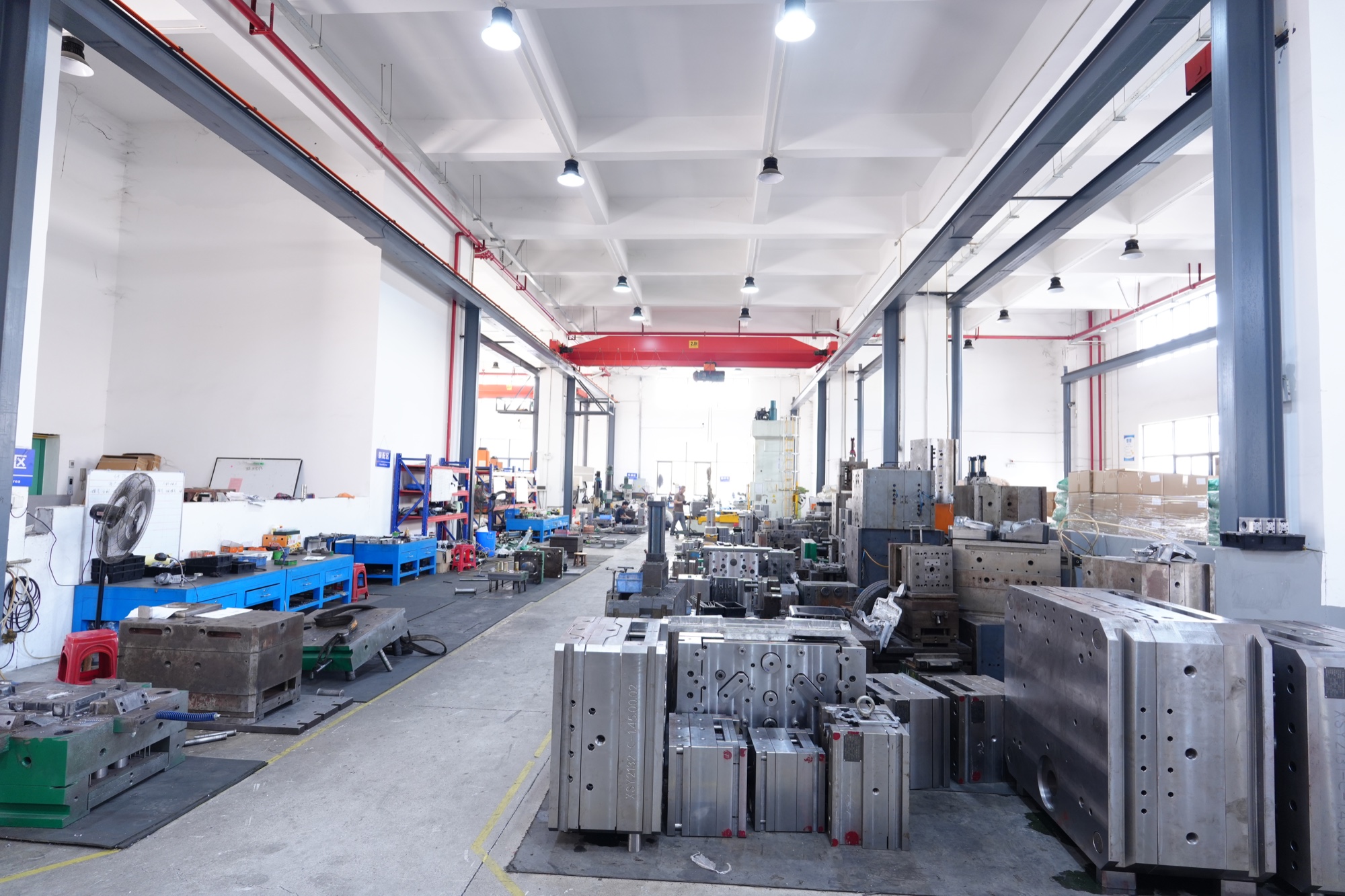
DIANLETE integrates product development, mold processing, injection production and manufacturing in Foshan. Select any image to inspect the original factory photograph.

DIANLETE factory complex in Foshan from DSC01128 original artwork
Factory Exterior · FoshanDIANLETE product development, tooling and manufacturing operations are coordinated from the Foshan production site.
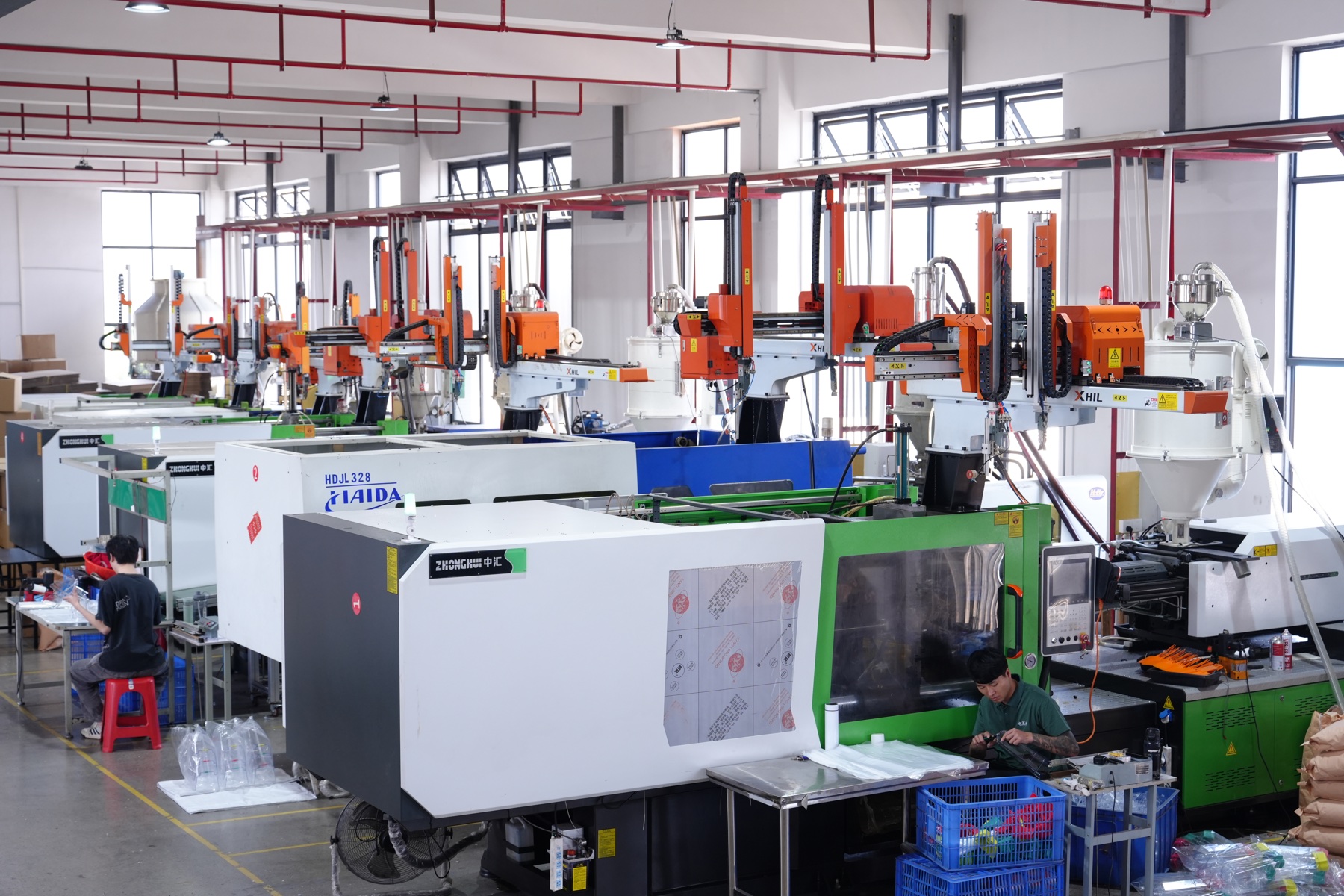
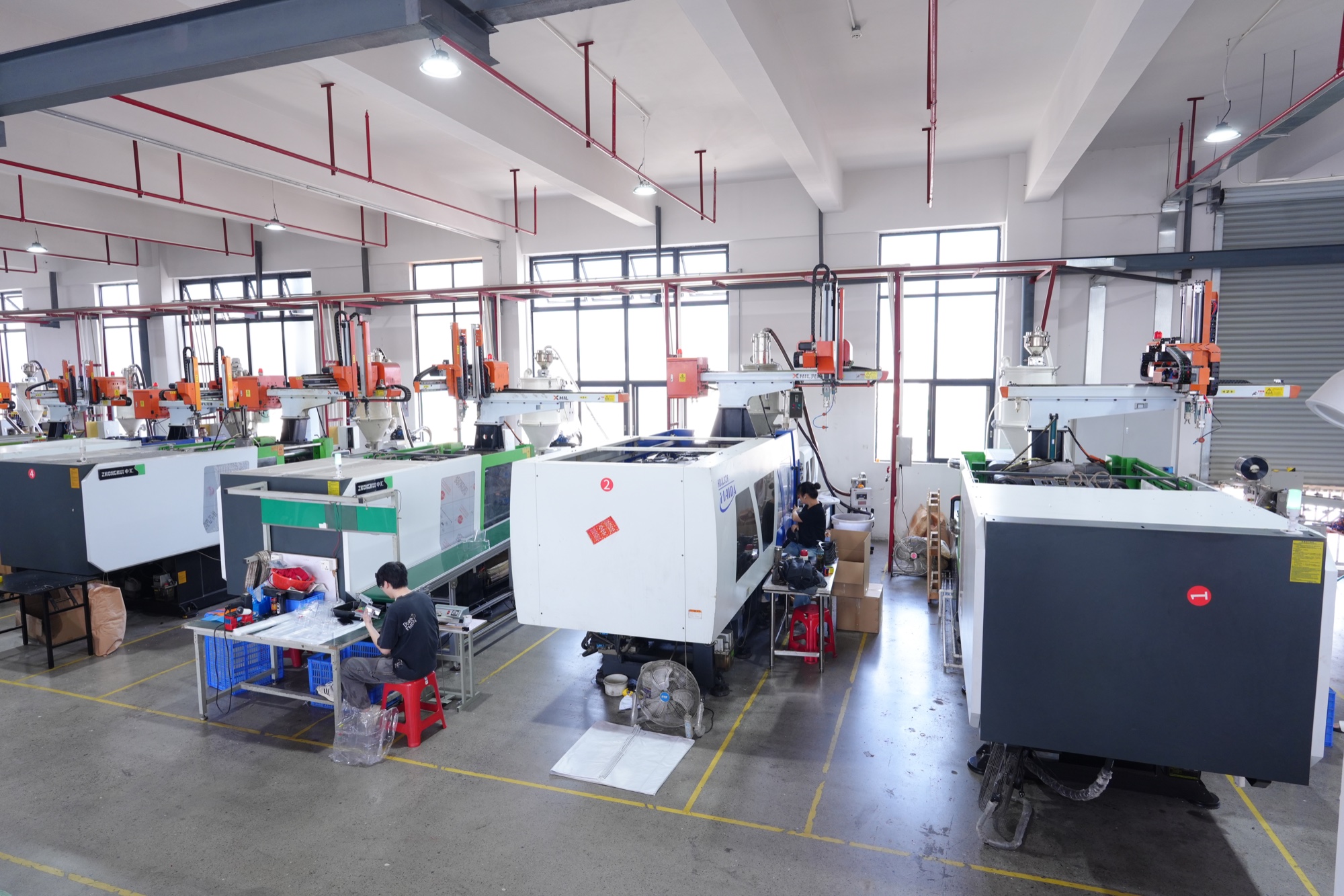
DIANLETE production floor with injection molding equipment
Integrated Production FloorInjection molding equipment supports repeatable production for standard covers, project orders and distributor supply.
DIANLETE factory building from DSC00871 original photograph
Factory CampusProduction, engineering and tooling resources are organized within the same manufacturing campus for faster coordination.
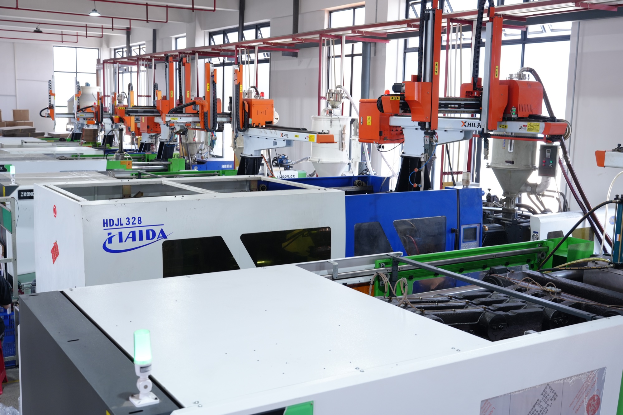
Injection molding line at DIANLETE factory
Injection Molding LineProcess settings and transparent PC material formulation can be evaluated for project environment and product geometry.
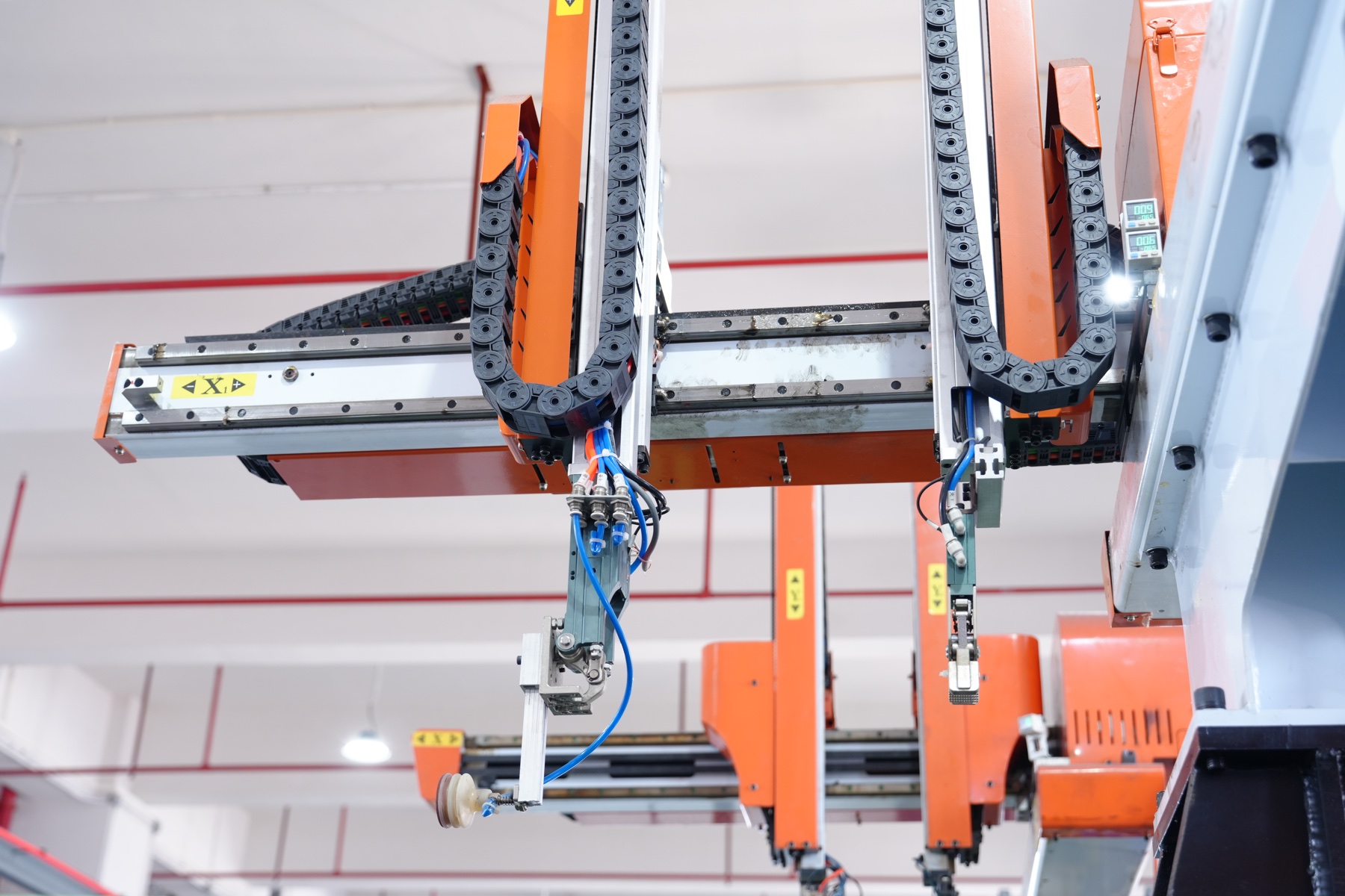
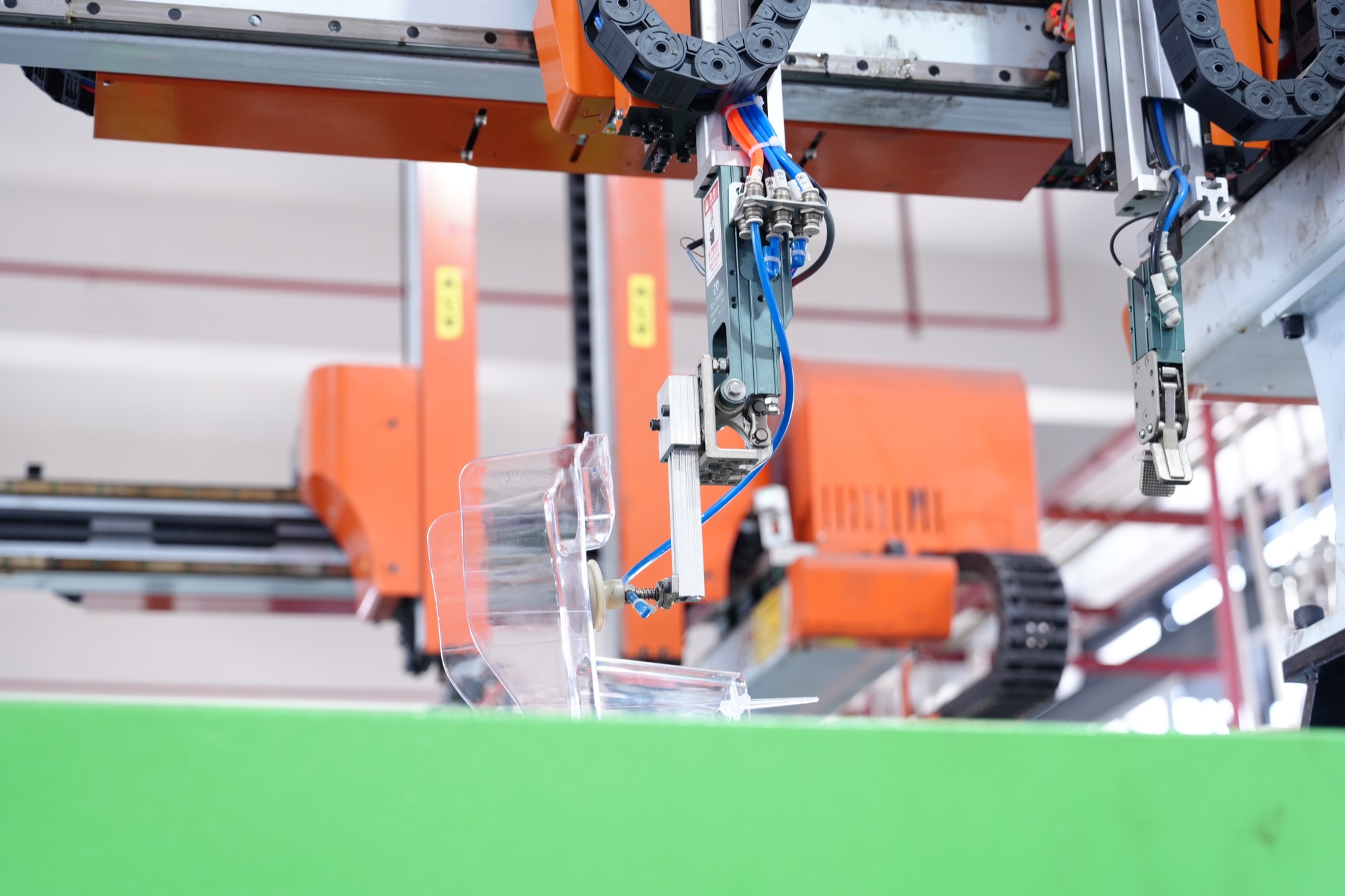
Automated production cell at DIANLETE
Automated Production CellAutomated handling improves production consistency while supporting controlled, repeatable manufacturing cycles.
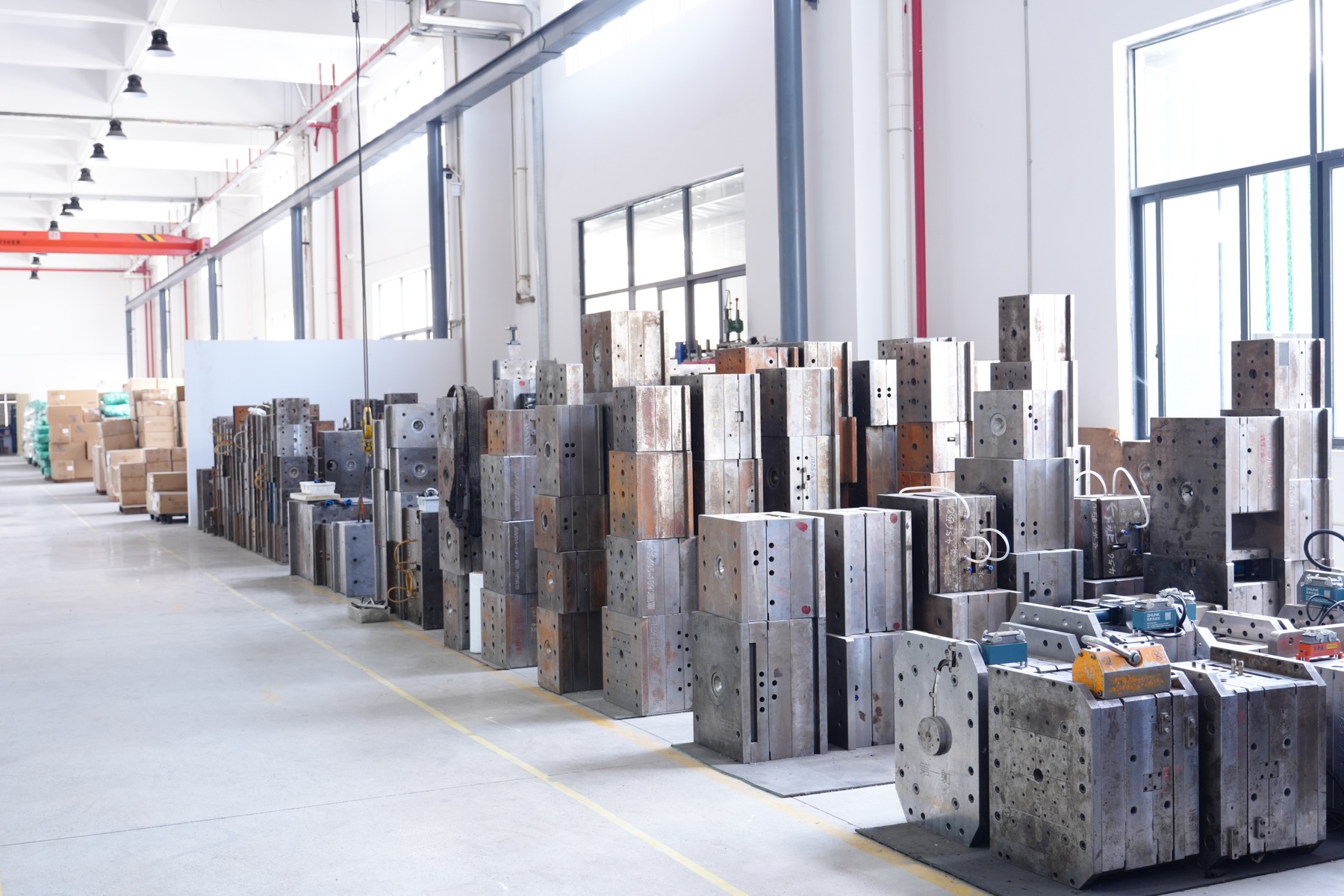
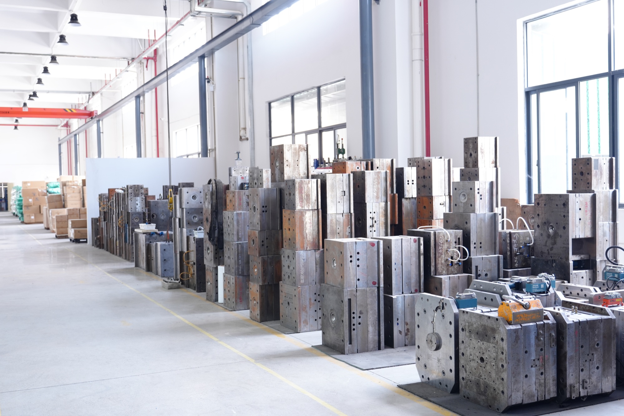
Organized mold and tooling storage
Mold & Tooling LibraryFactory-owned tooling supports standard product continuity and equipment-specific OEM or ODM development.
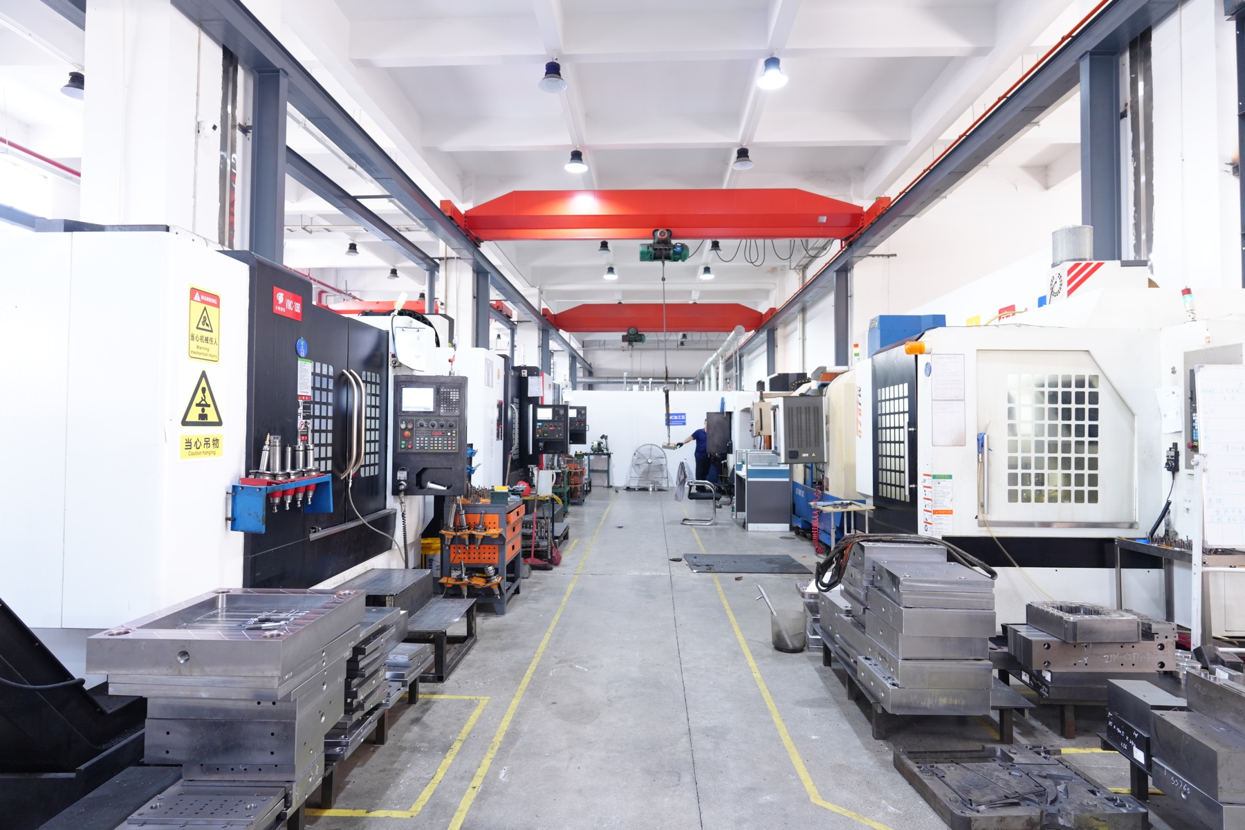
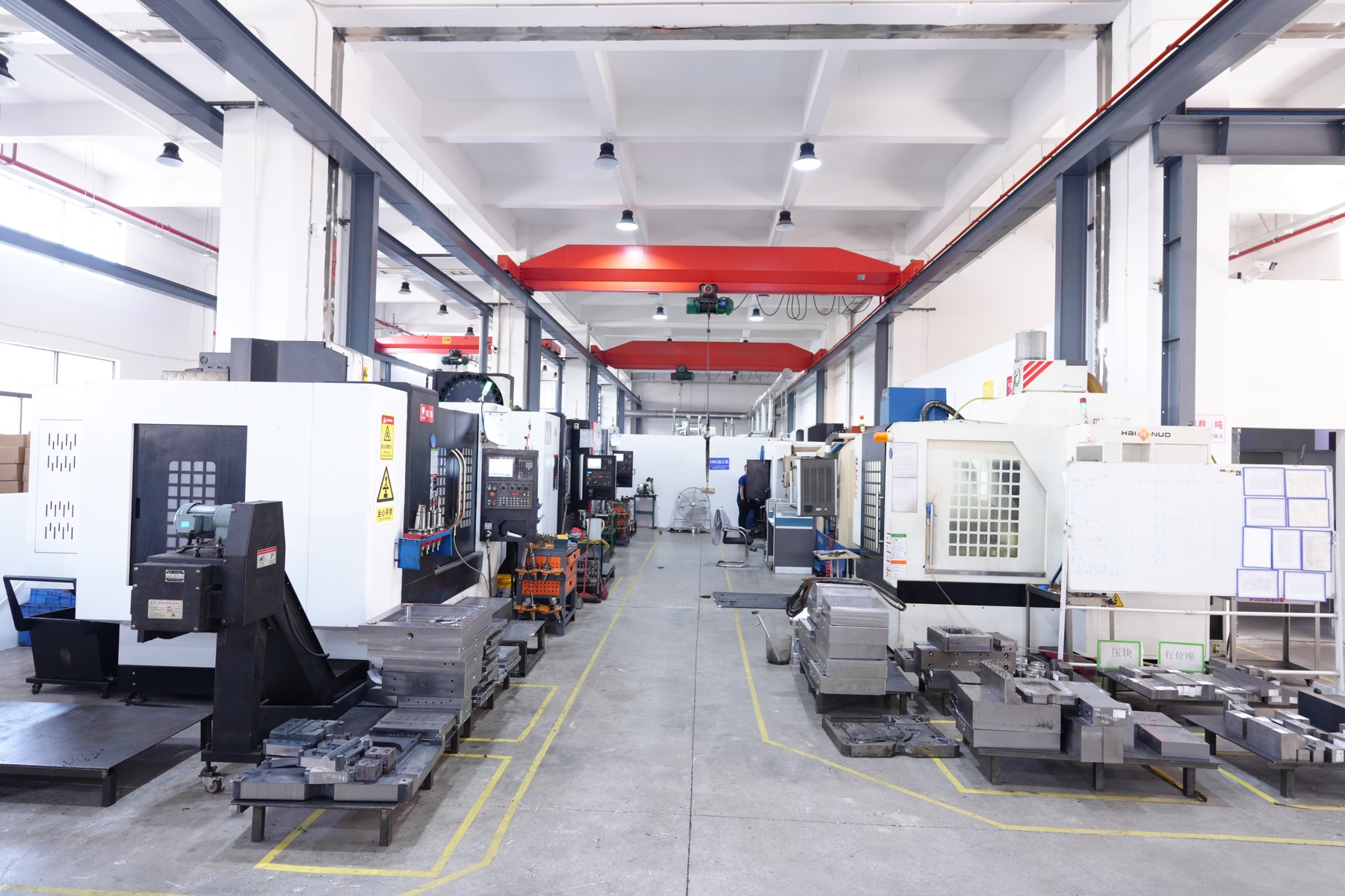
CNC machining aisle at DIANLETE
CNC Machining AisleMachining resources support mold development, fit correction and dimensional refinement during product engineering.
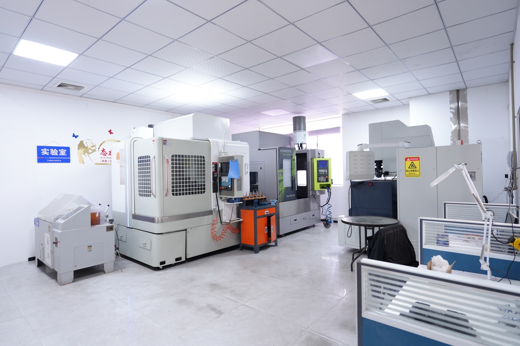
Precision machining center
Precision Machining CenterPrecision equipment is used to control tooling details required for secure fit, visibility and fastening performance.
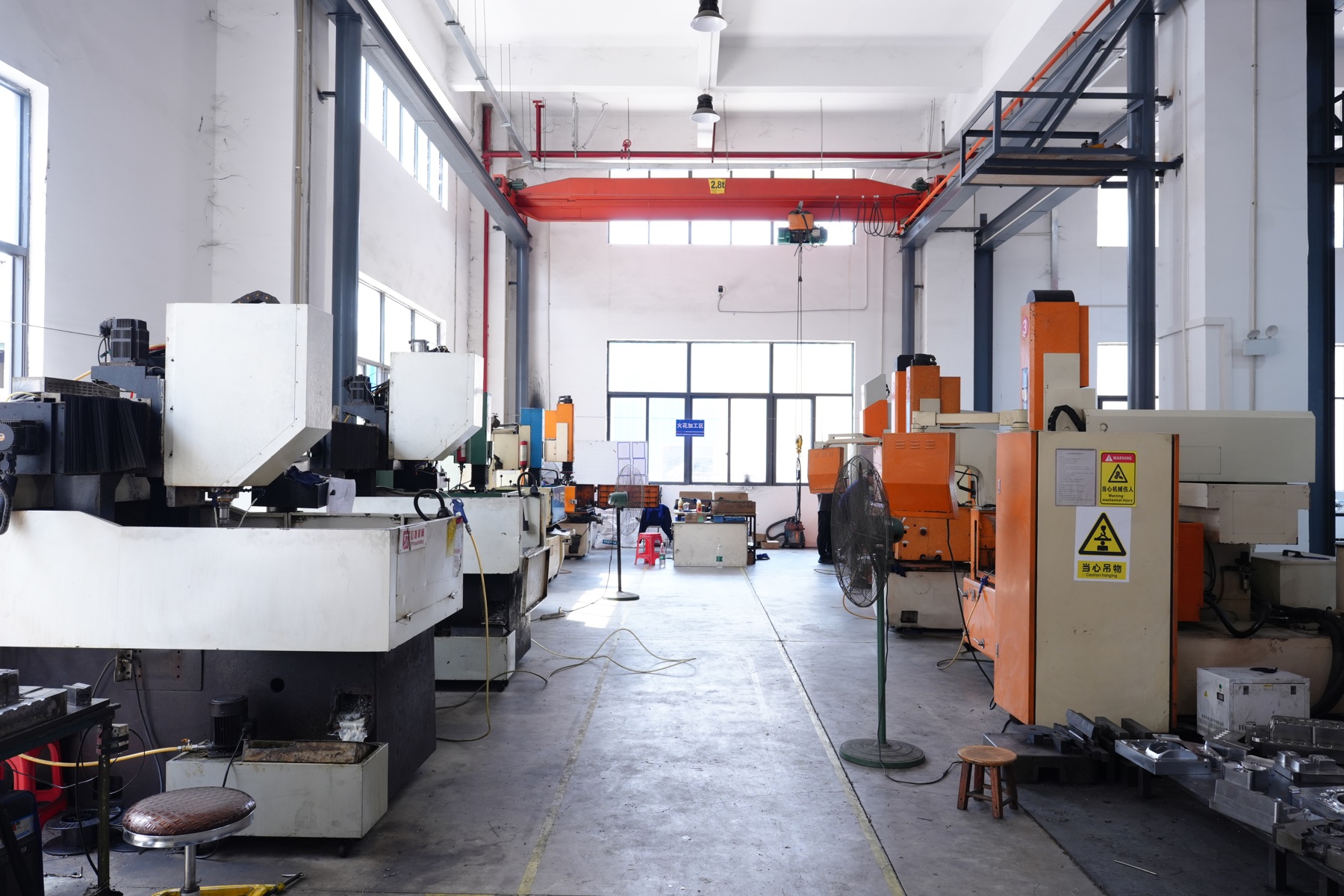
Tooling machine in DIANLETE workshop
Tooling development equipment
Precision equipment room
Wide view of the DIANLETE production workshop
Production workshop overview
Injection molding systems at the DIANLETE factory
Injection molding systems
Robotic material handling equipment on the production line
Robotic material handling
Mold tooling development floor at DIANLETE
Mold tooling development
DIANLETE technician carrying out quality inspection
In-process quality inspection
Precision manufacturing floor and equipment at DIANLETE
Precision manufacturing floor
01 / CONTROLFactory-owned development

Product geometry, tooling and production adjustments remain under direct manufacturing control.

02 / MATERIALApplication-specific PC formulation

Transparent rigid PC solutions can be evaluated for intense UV exposure, high heat or cold-region applications.

03 / DELIVERYOEM and ODM execution

From equipment review and prototyping to repeatable production for projects, distributors and standard products.

Factory Video Journal

Manufacturing evidence, updated in motion.

Production runs, tooling development, quality checks and field installations will be published as new DIANLETE footage becomes available, giving project teams a clearer view of how products move from engineering to delivery.

DIANLETE factory production floor video cover
Featured Factory Update

Inside DIANLETE Production

A replaceable factory media module for production runs, equipment updates and manufacturing capability.

Video 01 · Upcoming
Quality inspection video cover
Quality & Testing

Inspection in Practice

Process control, inspection and verification footage.
DIANLETE laboratory and equipment video cover
Laboratory & Tooling

Engineering in Motion

Material evaluation, tooling and equipment updates.

Original factory footage · DIANLETE manufacturing siteProduction / Quality / Installation / Project Updates
Installation Demonstration

Field installation, framed for every screen.

Landscape demonstrations present the full equipment and installation sequence, while vertical clips focus on fastening details, phase identification and close-range inspection for mobile viewing.

Landscape installation demonstration cover for DIANLETE insulation protective covers 16:9 Landscape
Complete Installation Sequence

Equipment Review to Visible Installation

Landscape format for reviewing equipment geometry, installation position and the completed visible protection system.

9:16 Vertical
Live-Line Installation

Insulated-Pole Cover Placement

Close-range vertical demonstration of protective-cover placement using an insulated operating pole.

9:16 Vertical
Field Procedure

Overhead Equipment Installation

Field-oriented vertical footage for distributor training, mobile review and installation reference.

Landscape and vertical formats support distributor training, field installation review and mobile technical sharing across project teams.

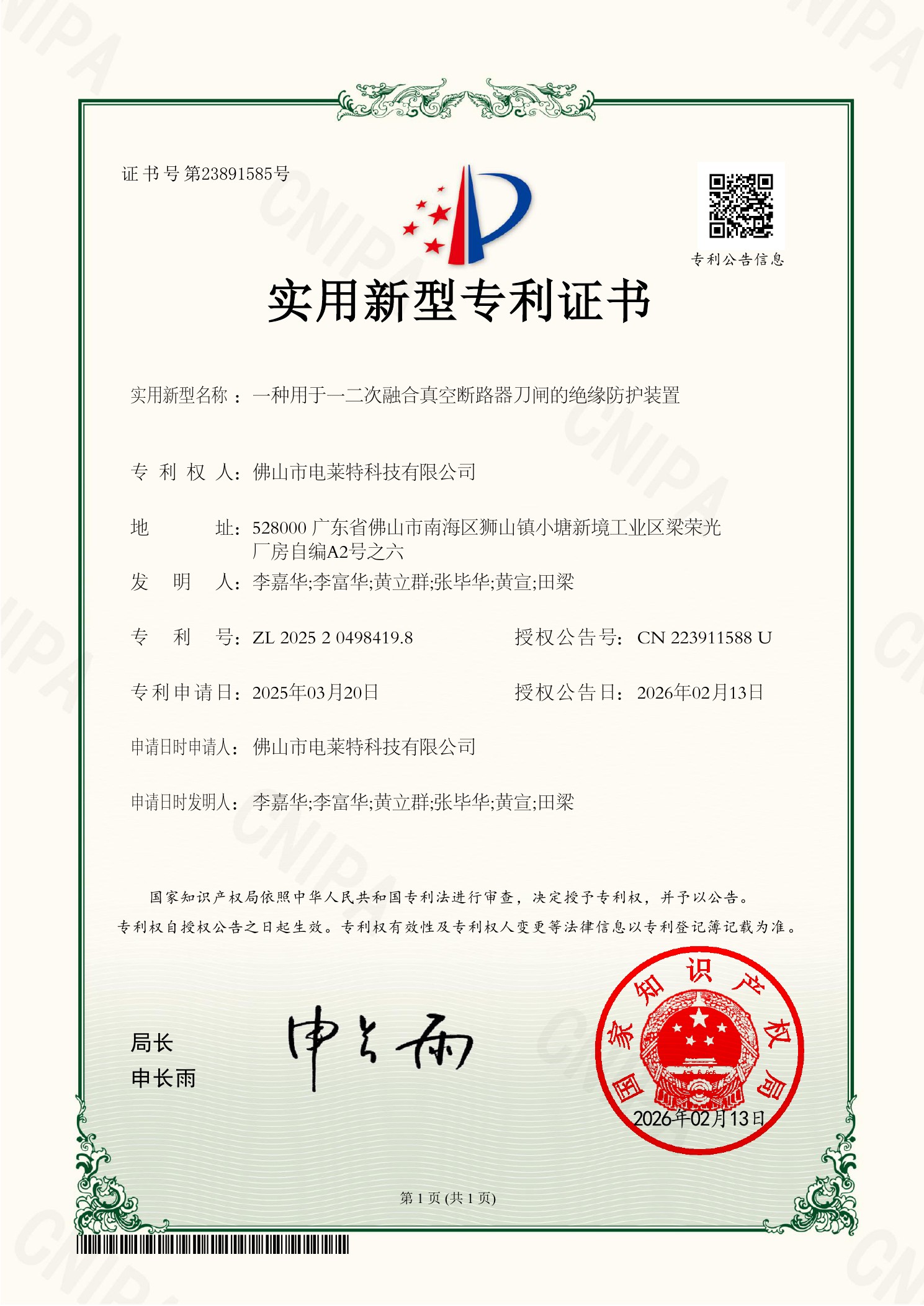
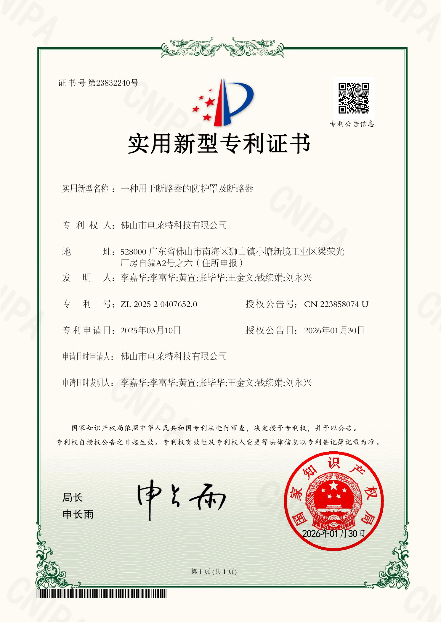
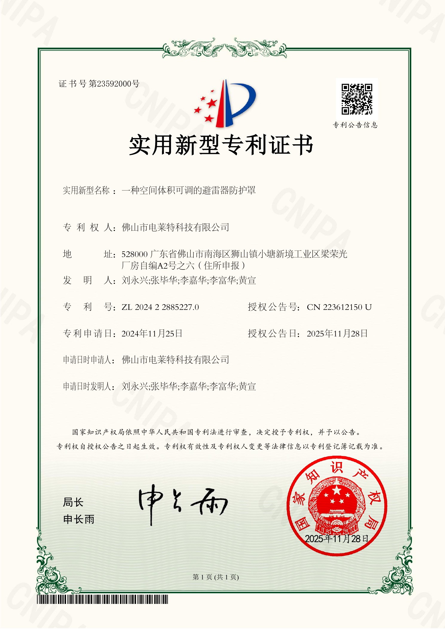
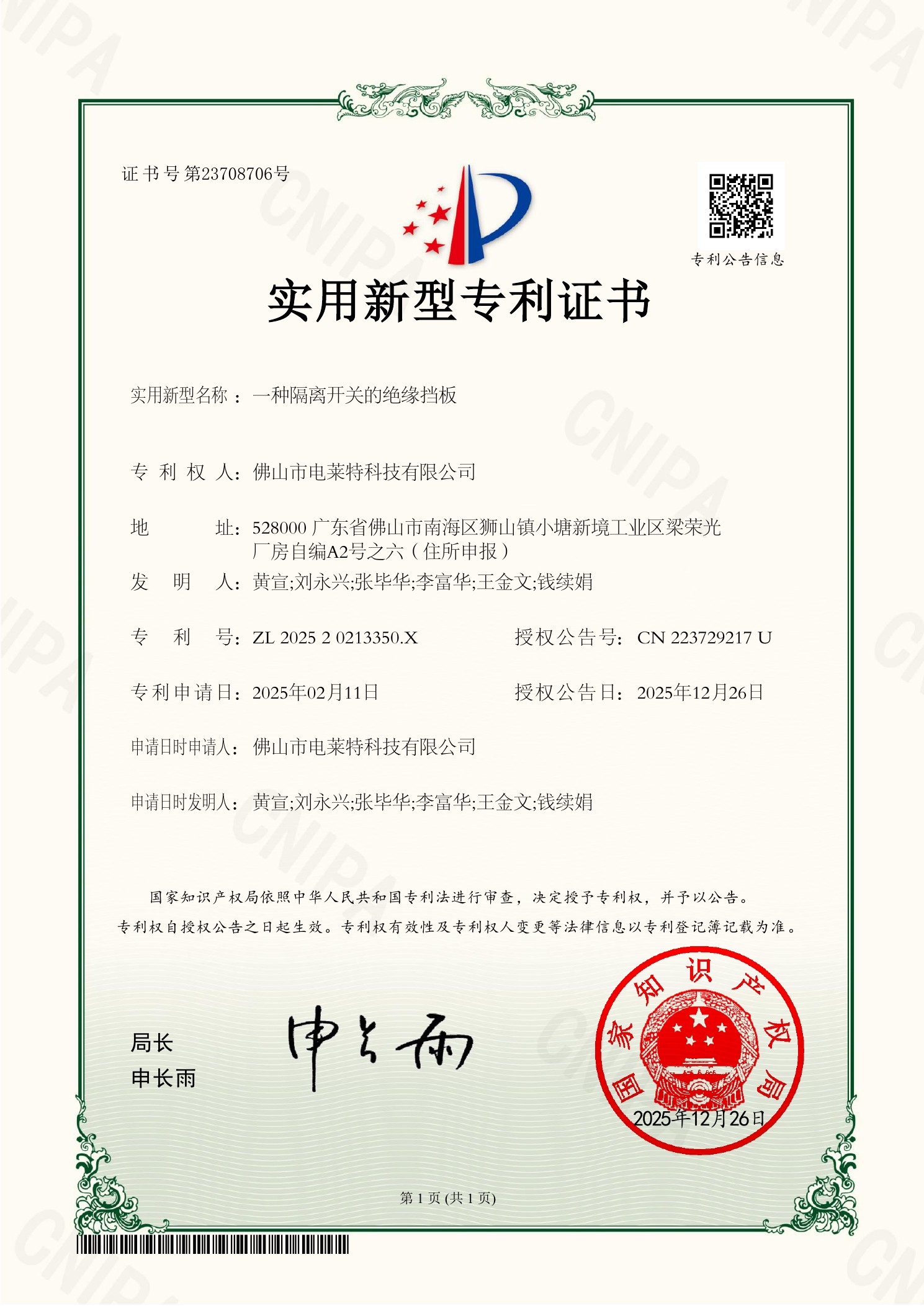
Credential Library

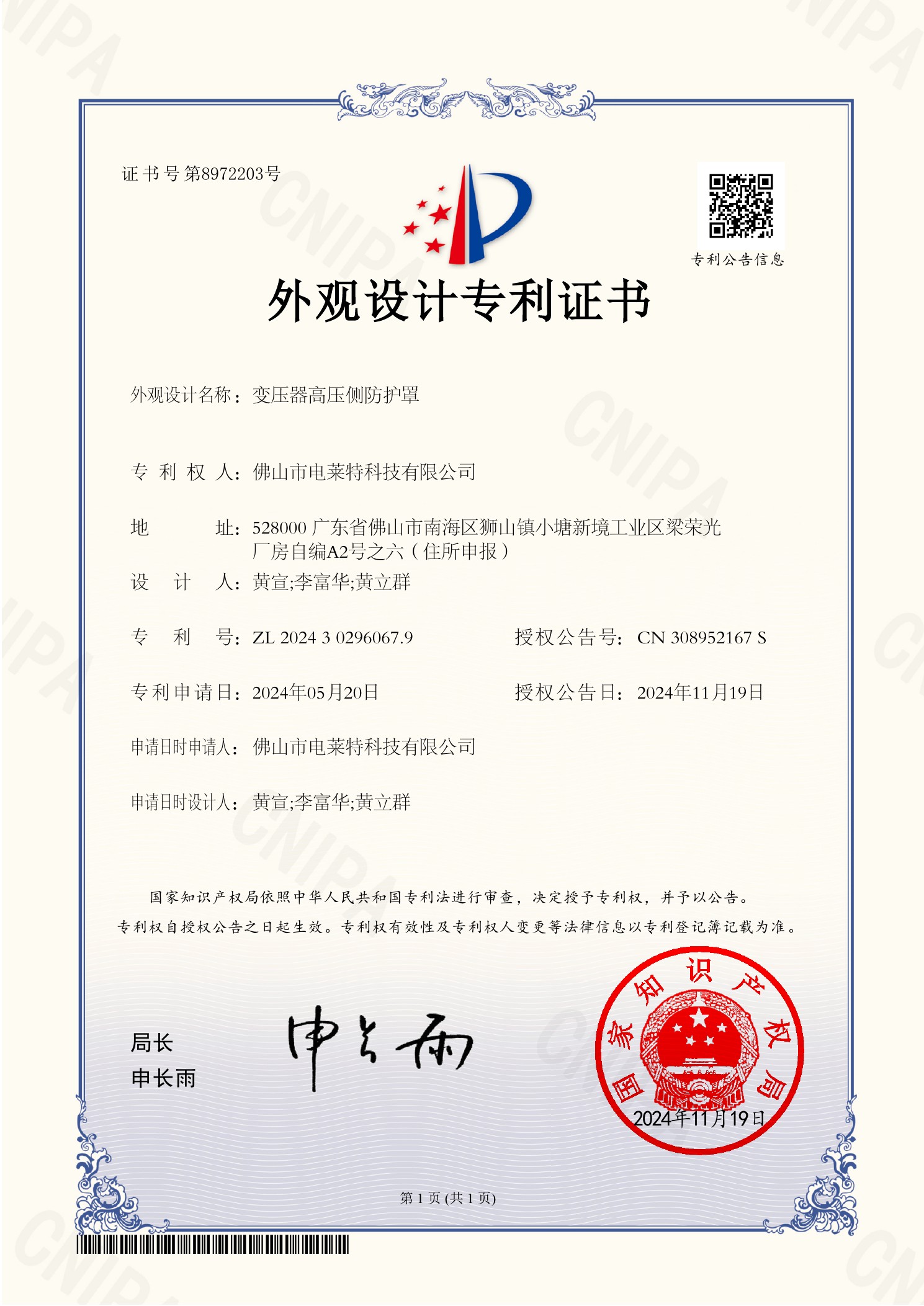
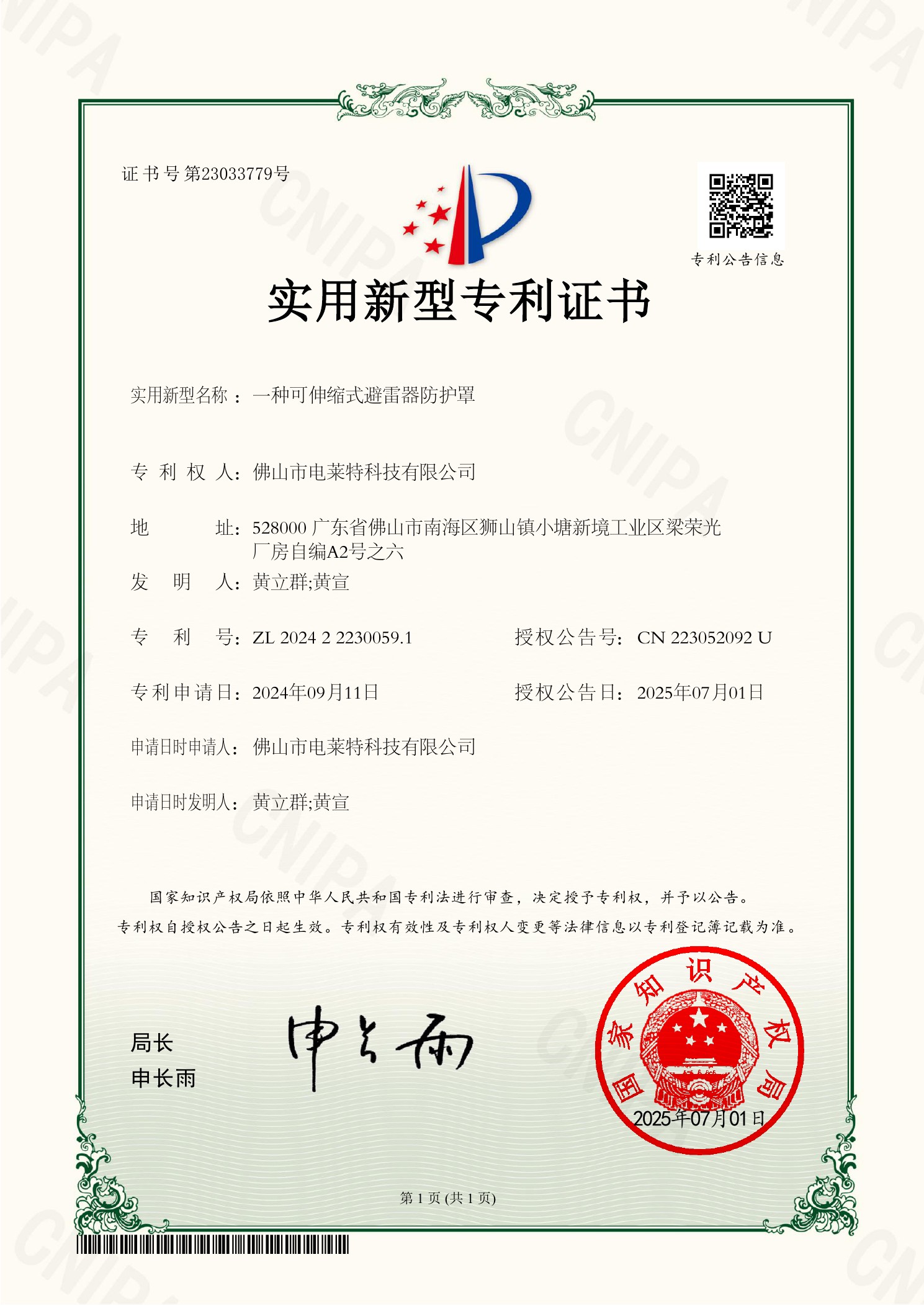
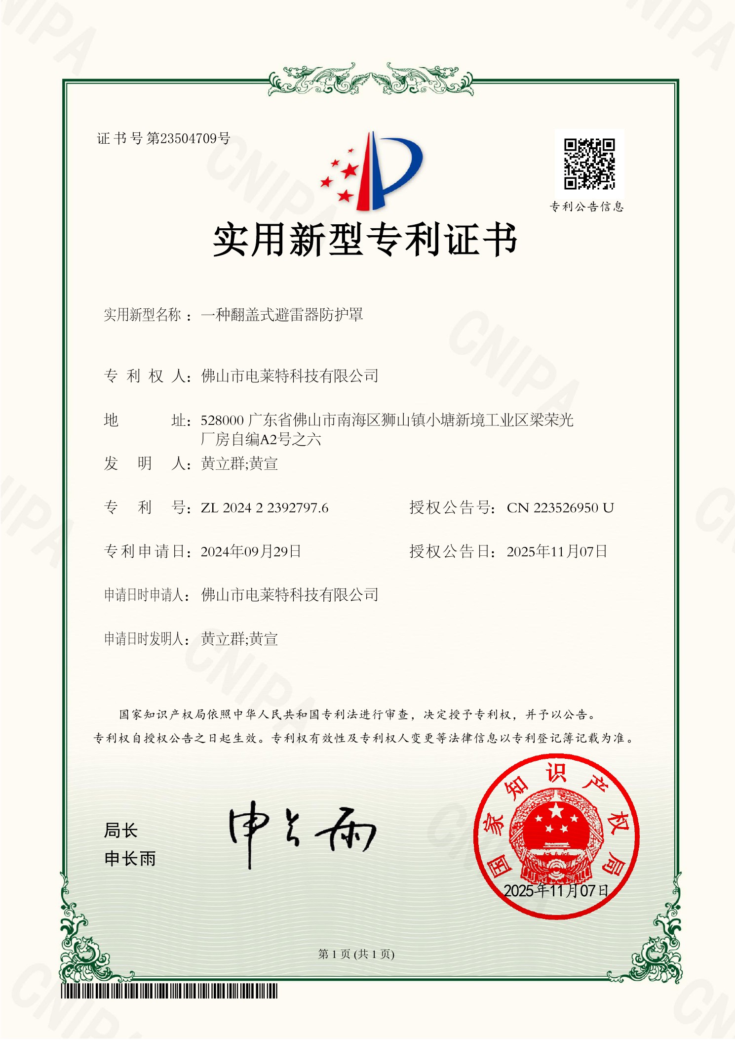
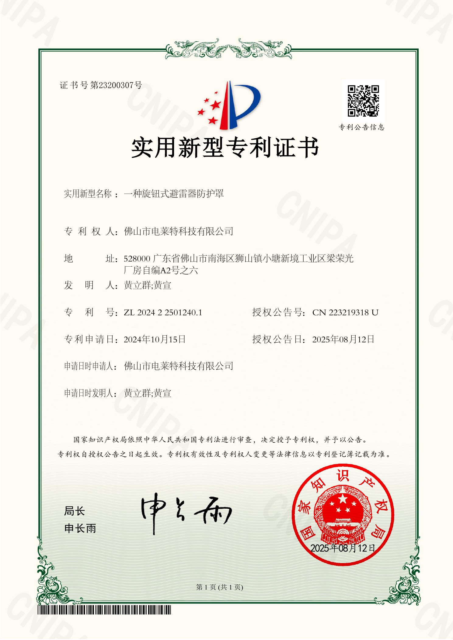
Documented systems. Patented products. Verifiable reports.

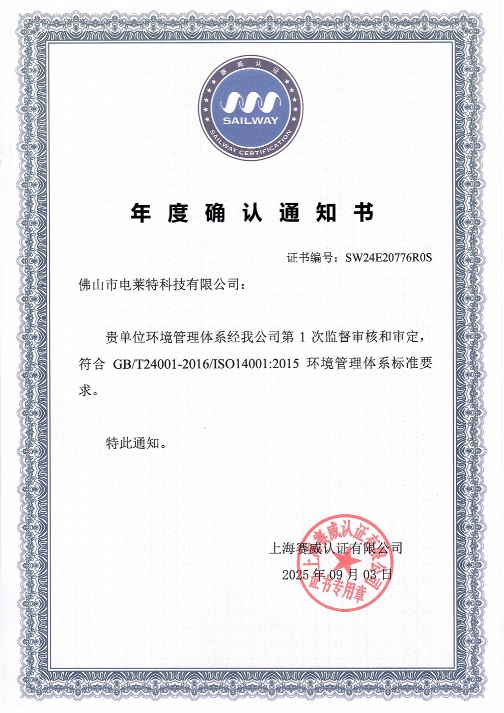
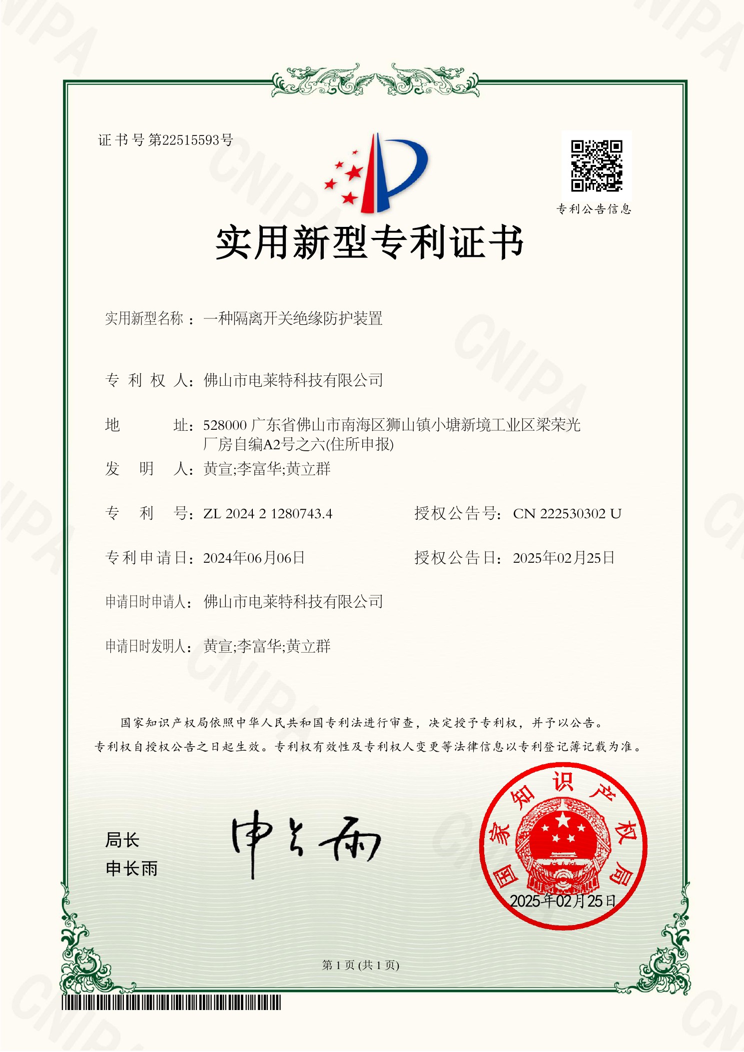
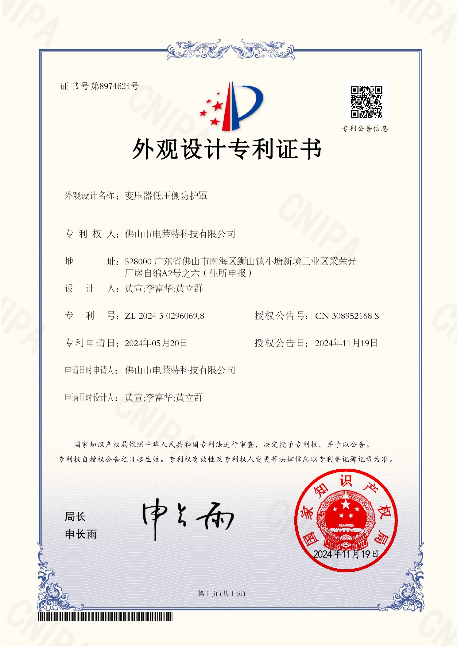
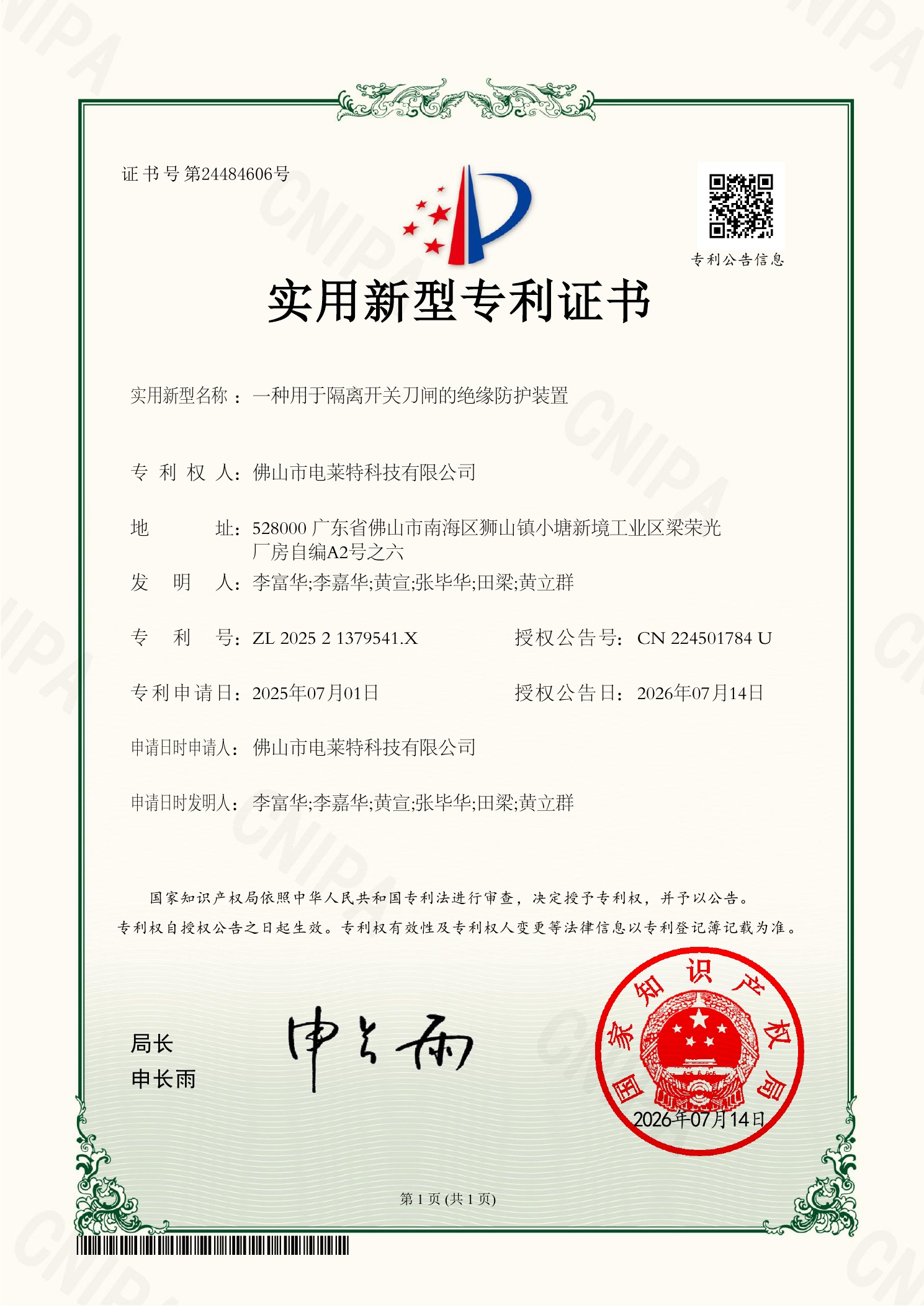
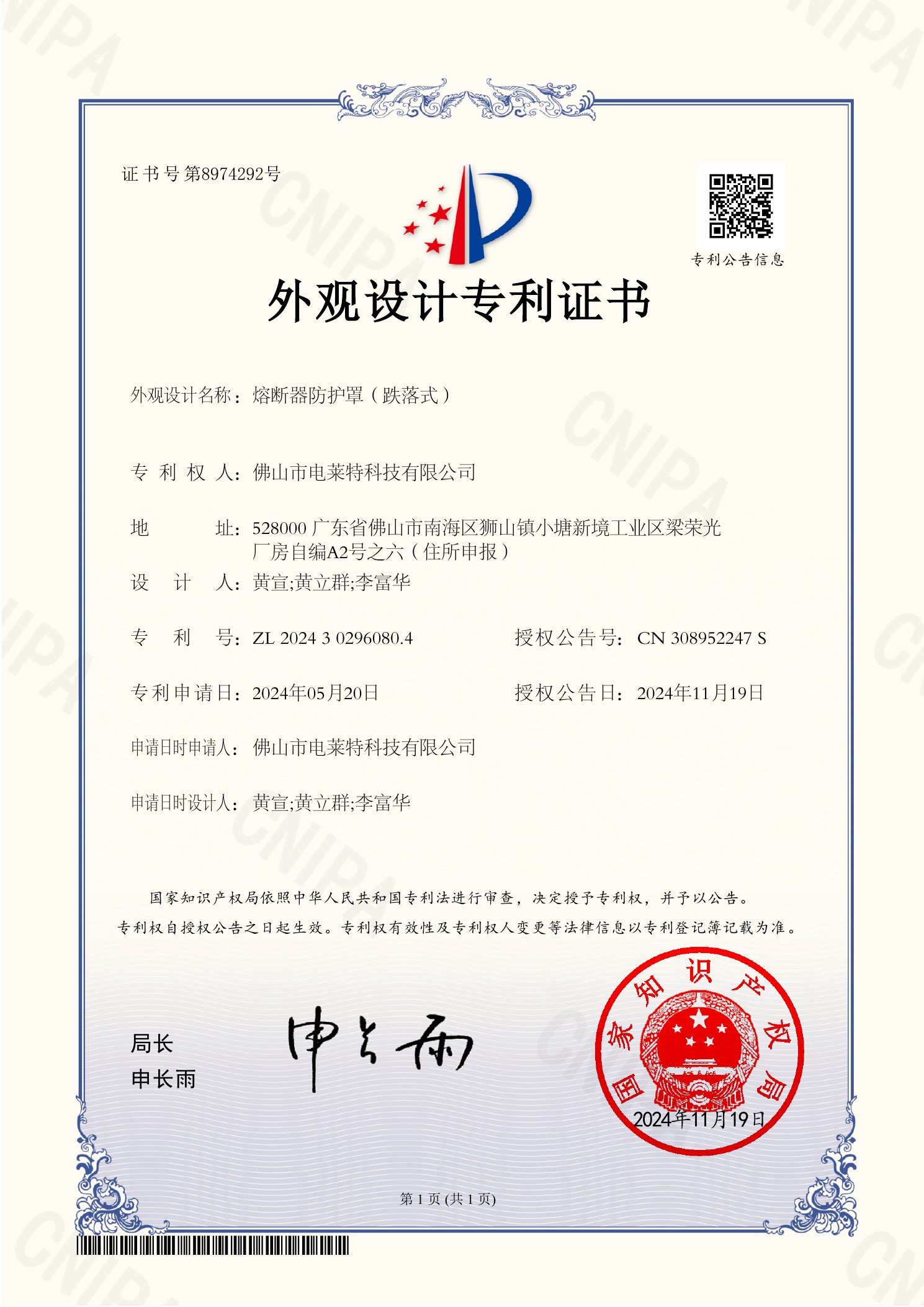
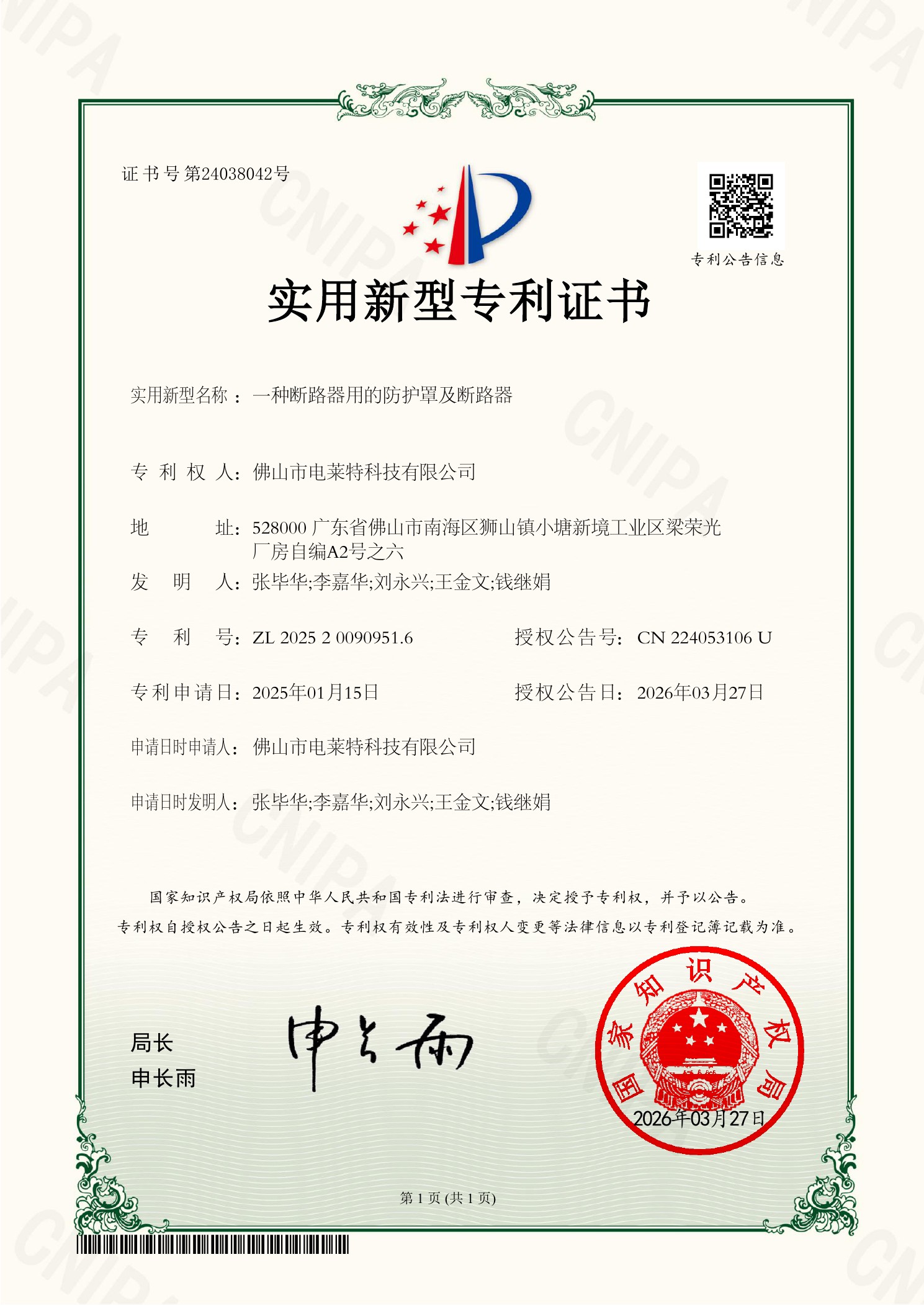
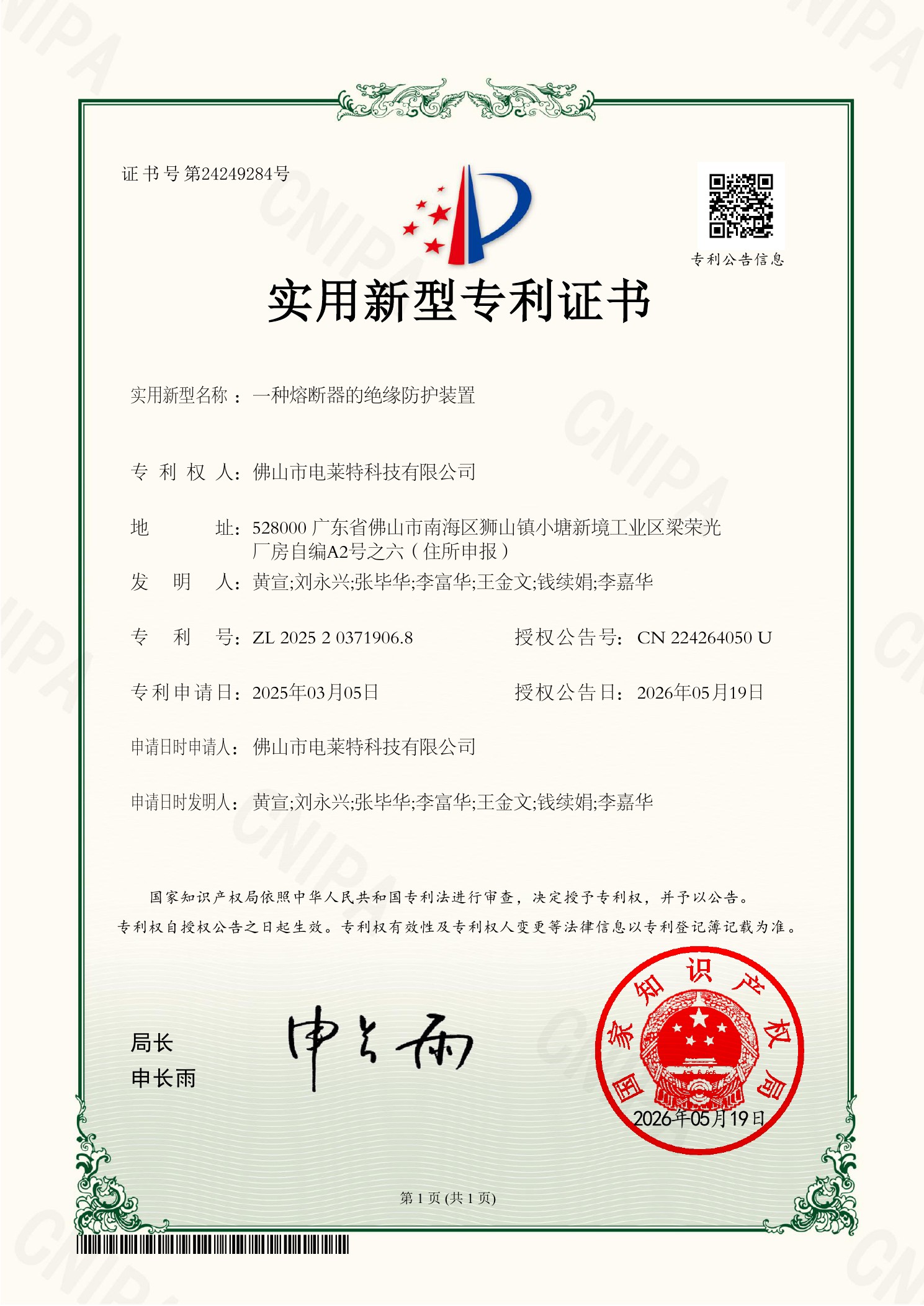
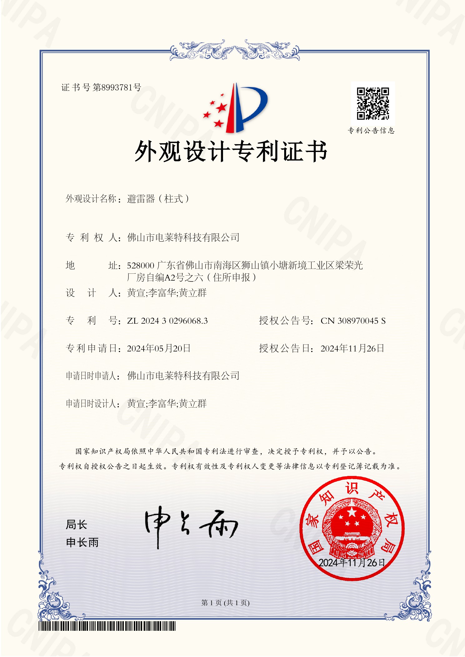
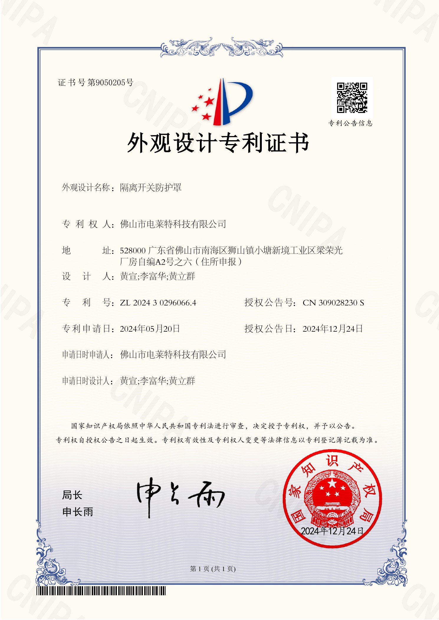
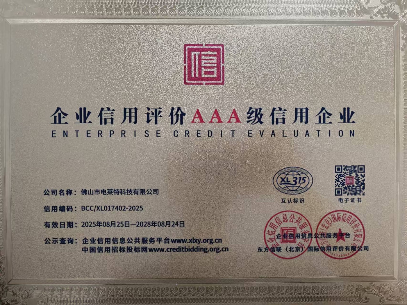
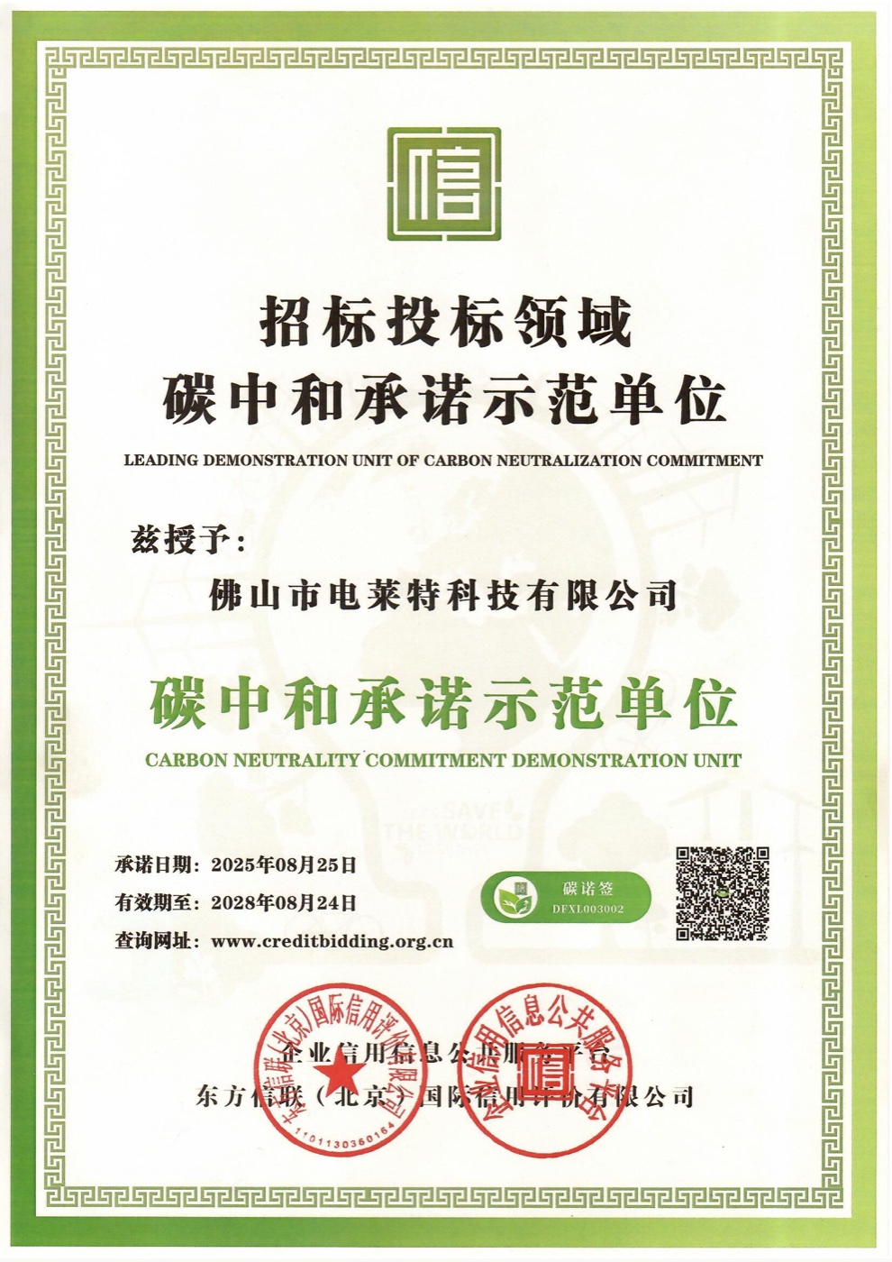
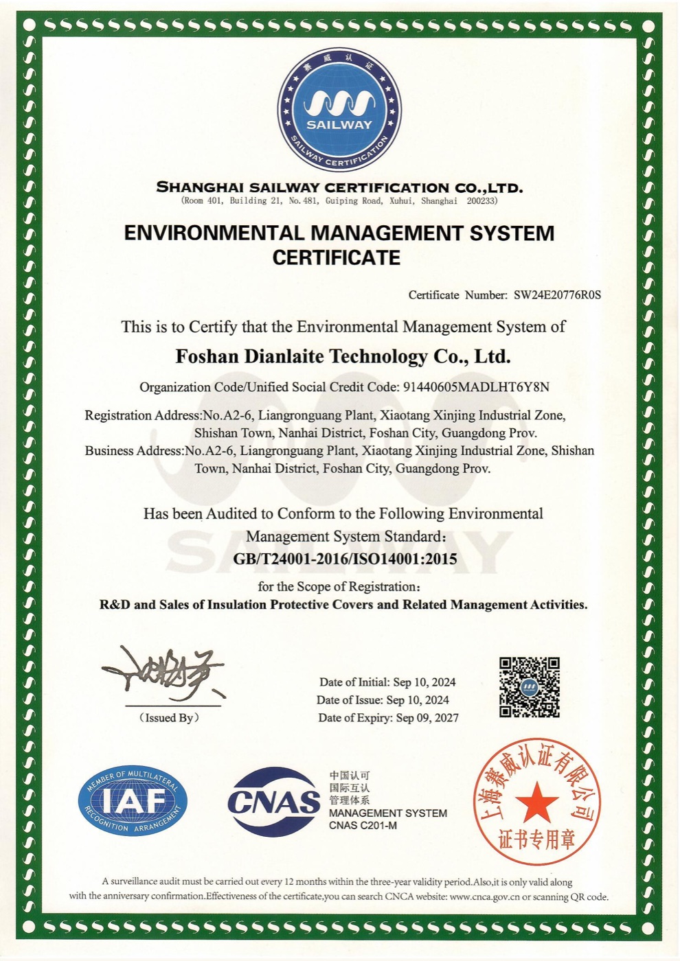
The library below uses the original documents supplied by DIANLETE. Switch categories to inspect management certificates, SGS reports, product patents and enterprise credit records. Select any document to open a larger view.

ISO 9001 quality management system certificate
ISO 9001 Quality ManagementEnglish certificate
ISO 14001 environmental management system certificate
ISO 14001 Environmental ManagementEnglish certificate
ISO 45001 occupational health and safety management system certificate
ISO 45001 Occupational Health & SafetyEnglish certificate
Quality management system annual confirmation
Quality System Annual ConfirmationCurrent verification record
Environmental management system annual confirmation
Environmental System Annual ConfirmationCurrent verification record
Occupational health and safety annual confirmation
OHS System Annual ConfirmationCurrent verification record
3 MANAGEMENT SYSTEMS3 ANNUAL CONFIRMATIONS2 SGS REPORTS16 PRODUCT PATENTS10 CREDIT RECORDS
Procurement & Service

Commercial terms built for trials, repeat orders and engineered projects.

DIANLETE separates standard retail purchases from volume and custom quotations, so buyers receive pricing and support appropriate to the actual product, quantity and technical risk.

Volume Discount Policy
01
Sample & trial orders

Standard retail pricing supports product evaluation and small-quantity procurement.

02
Repeat & volume orders

Quantity-based quotations are available for repeat buyers, distributors and project purchasing.

03
Project & OEM/ODM pricing

Custom geometry, materials, color coding, packaging, testing and delivery terms are quoted as one project package.

Discounts are confirmed in the formal quotation and are not automatically cumulative with other promotions.

After-Sales Service
01
Order traceability

Model, quantity and agreed technical requirements are checked against the confirmed order record.

02
Installation & issue review

Photos, video and equipment information are reviewed for installation guidance or verified quality and fit concerns.

03
Documented resolution

Replacement, rework, credit or another agreed solution is determined from the evidence and confirmed order terms.

For transport damage or shortages, retain the packaging and submit order details and visual evidence promptly after delivery.

Technical FAQ

Visible insulation protection, explained.

What is a visible insulation protective cover?

It uses a transparent protective structure around exposed power equipment connection points, allowing installation position, phase identification and equipment condition to remain observable.

Can DIANLETE covers support live-line operation requirements?

DIANLETE develops protective covers for live-work applications. The submitted PC sample is identified in SGS report GZMR250400993701 as an insulated protective cover for live work. Final selection must match the equipment and project requirements.

Why use three-phase or three-phase four-wire color-coded components?

Color separation makes each phase easier to recognize during installation and inspection. Together with a transparent cover, it supports clearer visual confirmation and helps reduce identification errors.

Can insulation covers help protect power equipment from squirrels, birds and small animals?

Equipment-specific insulation and wildlife protection covers can help limit animal access to exposed connection points and reduce contact-related short-circuit, flashover and outage risks. Product geometry, clearances and material selection must be reviewed for the actual equipment, wildlife exposure and environment.

Are OEM and ODM insulation covers available?

Yes. Upload equipment photos, dimensions or drawings through the customization form. DIANLETE can evaluate cover geometry, fitting position, fastening structure, phase identification and material requirements.

Can DIANLETE develop 15kV covers for North America?

Custom 15kV solutions can be evaluated against the equipment and project requirements. Applicable North American certification standards and testing requirements are discussed and agreed separately before any compliance claim is made.

Does DIANLETE offer volume discounts?

Yes. Sample and small-quantity orders use retail or trial-order pricing. Repeat, distributor and project orders receive quantity-based quotations according to model, quantity, packaging, customization, testing and delivery terms.

What after-sales support is available?

DIANLETE provides order traceability, installation guidance, arrival inspection support and engineering review for verified quality or fit issues. Keep the packaging and submit the order details, photos and video evidence so the issue can be assessed against the confirmed quotation, drawings and order terms.

Custom Engineering Request

Upload the equipment. Start with technical facts.

Send field photos, dimensions or engineering drawings. DIANLETE will review fit, voltage class, phase identification, installation method and environmental conditions before recommending a standard product or custom development path.
01
Upload reference filesEquipment photos, PDF drawings, DWG or DXF files.
02
Engineering reviewGeometry, material, environment and installation requirements.
03
Technical responseRecommended solution, clarification points and quotation path.

Submit a customization request

Fields marked * are required. Your files will be handled as project reference material.

Voltage class *
Photos or drawings *

For North American 15kV projects, applicable certification standards and testing requirements will be evaluated and agreed separately. No certification claim is made until the required assessment is completed.

WAWhatsApp Inquiry
WhatsAppRequest a Quote